
A kind of pet imaging rod source device and pet equipment

A rod source and imaging technology, applied in the field of medical equipment, can solve the problems of increasing the maintenance cost of the operator, reducing the effective running time of the equipment, and the complex calibration process. Effect

Active Publication Date: 2017-10-24
THE WUHAN DIGITAL PET CO LTD
View PDF10 Cites 0 Cited by
  • Summary
  • Abstract
  • Description
  • Claims
  • Application Information

AI Technical Summary

Problems solved by technology

[0007] Usually, it takes an average of 1.5 working days to complete all the above-mentioned calibration work. The calibration process is more complicated and time-consuming, which greatly reduces the effective running time of the equipment; at the same time, the disassembly and assembly of the rod source device requires special tooling Carried out, increasing the maintenance cost and the work intensity of the operator

Method used


Image

  • A kind of pet imaging rod source device and pet equipment
  • A kind of pet imaging rod source device and pet equipment
  • A kind of pet imaging rod source device and pet equipment

Examples


Embodiment Construction

[0039] The present invention will be further described below in conjunction with the embodiments shown in the accompanying drawings.

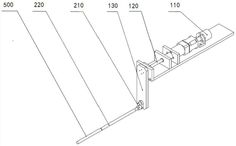
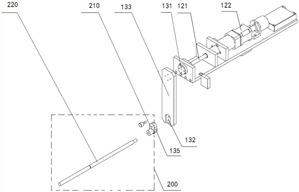
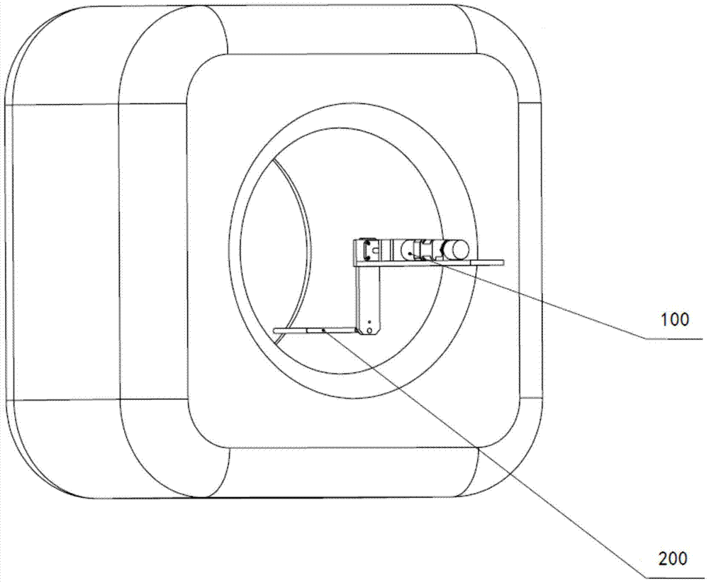
[0040] Such as Figure 1 to Figure 5 As shown, the present invention discloses a rod source device for PET imaging, including a rod source body 500, a first rotation module 100 that drives the rod source body 500 to rotate around the axial direction at a uniform speed, and a second rotation module that drives the rod source body 500 to rotate 200.

[0041] The first rotating module 100 includes a first power assembly 110, a first transmission assembly 120, and a rotating arm structure 130. The first power assembly 110 is arranged parallel to the axial direction, and the rotating arm structure 130 is arranged perpendicular to the axial direction, that is, parallel to the PET host. The height direction is set, the first power assembly 110 is connected to the rotating arm structure 130 via the first transmission assembly 120, the output end of th...


PUM


Abstract

Disclosed is a PET imaging rod source device, comprising a rod source body (500), a first rotating module (100) for driving the rod source body (500) to rotate around the axial direction at a uniform speed, and a second rotating module (200) for driving the rod source body (500) to rotate around the centre-axis, wherein the first rotating module (100) comprises a first power assembly (110), a first transmission assembly (120) and a rotating arm structure (130); the first power assembly (110) is parallel to the axial direction; the rotating arm structure (130) is perpendicular to the axial direction; the first power assembly (110) and the rotating arm structure (130) are in transmission connection via the first transmission assembly (120); the second rotating module (200) is fixed at the end of the rotating arm structure (130) far away from the first transmission assembly (120); an output end of the second rotating module (200) is parallel to the axial direction; and the output end of the second rotating module (200) is directly connected to the rod source body (500) to drive the rod source body (500) to rotate around the centre-axis, and at the same time follows the movement of the first power assembly (110) to drive the rod source body (500) to rotate around the axial direction, so that all detector units can be more uniformly irradiated when the rod source body (500) is subjected to normalization correction, and a more accurate correction result is obtained.

Description

technical field [0001] The invention relates to the technical field of medical devices, in particular to a correction structure applied to a PET imaging device. Background technique [0002] In the field of nuclear medicine, PET (Positron Emission Computed Tomography) is an imaging technique that can non-invasively display the function and metabolism of human organs. In clinical practice, this technique can be used to guide cancer treatment. The principle is: the malignant tumor tissue metabolism in the patient's body is vigorous, and the metabolites (such as glucose, protein, etc.) gather more. We can use radionuclides (such as 18F, 11C, etc.) to label metabolites, and then use a PET imaging system to accurately display the aggregation and activity of metabolites through three-dimensional imaging technology to reflect the activities of life metabolism. PET can also be integrated with CT on one instrument to form a PET-CT system (integrated PET-CT system). PET-CT mainly inc...

Claims


Application Information

Patent Timeline
Patent Type & Authority Patents(China)
IPC IPC(8): A61B6/03
CPCA61B6/03G01T1/161
Inventor 王浩张建兵
Owner THE WUHAN DIGITAL PET CO LTD
Learn More