
A spraying equipment for the inner wall of a circular pipe

A technology of spraying equipment and round tubes, applied in the direction of spraying devices, etc., can solve the problems of spray gun failure, short circuit, inconvenient operation, etc., and achieve the effects of saving power consumption, saving equipment costs, and wide application range

Active Publication Date: 2017-03-22
WUHU DINGHENG MATERIAL TECH
View PDF4 Cites 0 Cited by
  • Summary
  • Abstract
  • Description
  • Claims
  • Application Information

AI Technical Summary

Problems solved by technology

[0002] Generally speaking, for some high-precision instruments or devices, supersonic spraying of nanomaterials is often required on the surface, but some devices are inconvenient to spray due to shape problems, especially the inner wall of the round tube, manual spraying is not only The operation is very inconvenient, and the quality of spraying is also very low
[0003] For the above problems, some people have also come up with the idea of ​​controlling the spray gun in an automated way to spray the inner wall of the circular tube. The specific method is to use the corresponding power components and transmission equipment to synchronously control the spray gun to rotate and feed. The movement like spring stroke, the spraying in this way not only has good spraying quality, but also has a high degree of automation and is very convenient to control, but the problem is that although the spray gun can complete such a movement, the power line and nanomaterial supply line connected to the back end of the spray gun are in this way. Under the action of repeated unidirectional rotation, the power line and nanomaterial supply line will often be knotted and hanged, which will lead to greater safety hazards such as spray gun failure or line short circuit.

Method used


Image

  • A spraying equipment for the inner wall of a circular pipe
  • A spraying equipment for the inner wall of a circular pipe
  • A spraying equipment for the inner wall of a circular pipe

Examples


Embodiment Construction

[0036] In order to make the technical means, creative features, goals and effects achieved by the present invention easy to understand, the present invention will be further elaborated below.

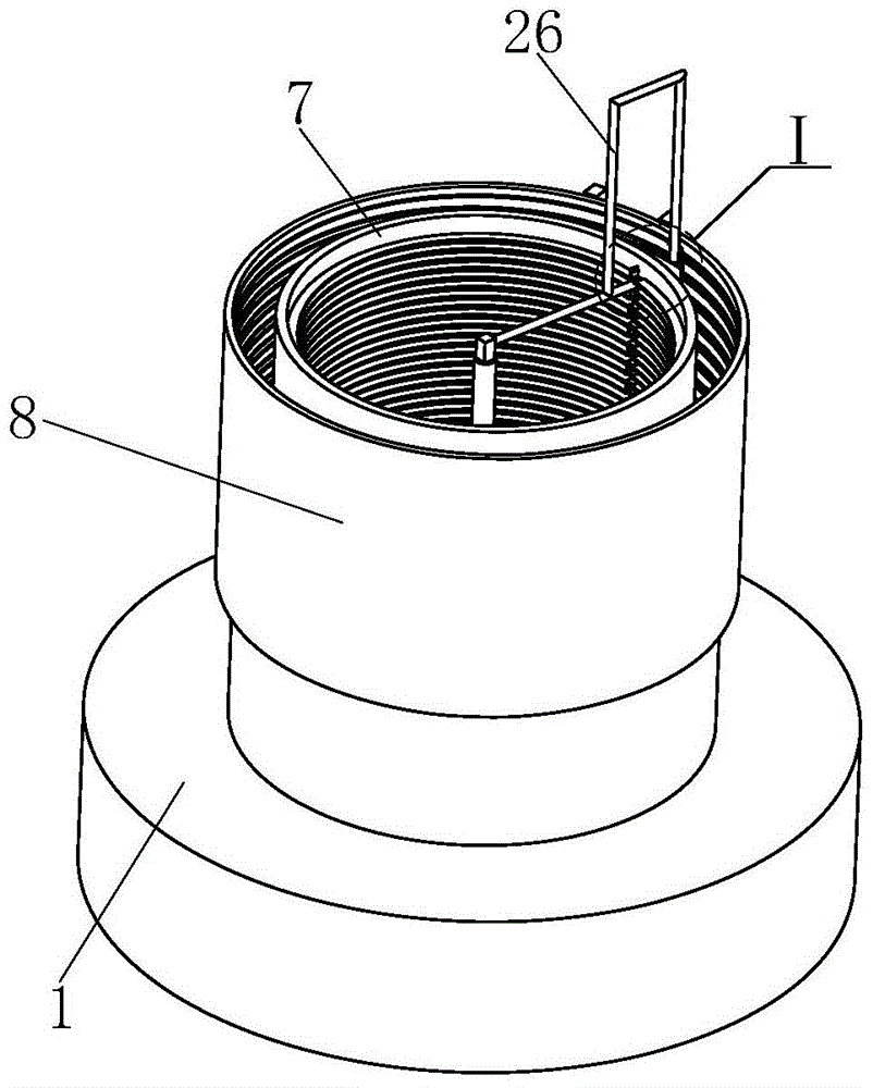
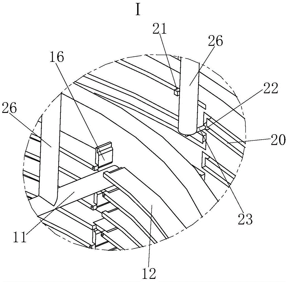
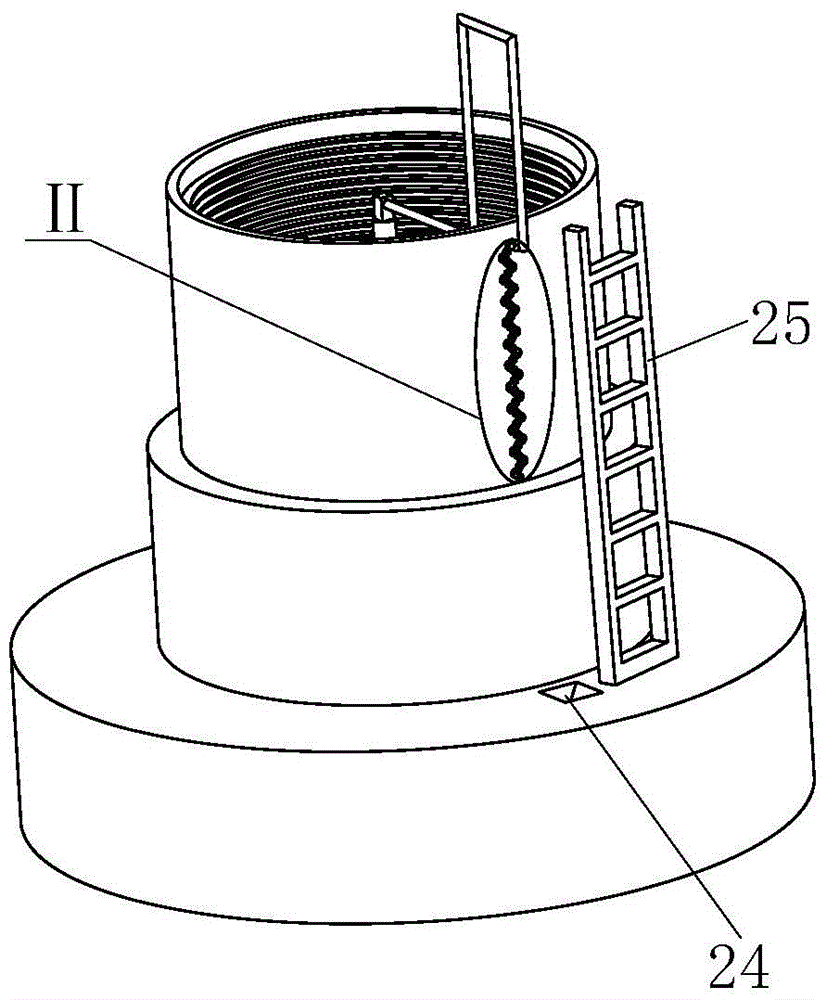
[0037] Such as Figure 1 to Figure 11 As shown, a spraying equipment for the inner wall of a circular pipe mainly includes a base 1, the middle part of the base 1 has a mounting cylinder 2, and the outside of the mounting cylinder 2 is sequentially provided with an inner frame support 7 and an outer frame support 8 , the inner bottom of the installation cylinder 2 is provided with a backing plate 3, and the inner upper end of the installation cylinder 2 is provided with an inner rail 4 formed by the intersection of circular grooves arranged at equal longitudinal intervals and two longitudinally extending longitudinal slideways, The upper part of the installation cylinder 2 has a positioning cover 5, the lower end of the positioning cover 5 has a block 5a adapted to the inner rail 4, and...


PUM


Abstract

The invention relates to spraying equipment for an inner wall of a circular tube. The spraying equipment mainly comprises a base, a mounting cylinder, an inner-frame support and an outer-frame support, wherein a subplate is arranged in the mounting cylinder; the upper end of the mounting cylinder is provided with an inner rail; the upper part of the mounting cylinder is provided with a positioning cover, and the lower end of the positioning cover is provided with a fixture block; a spray gun is arranged above the positioning cover, and is connected with a lateral extension frame; the inner side of the inner-frame support is provided with a sliding rail fame, and the sliding rail fame is provided with a falling gap; two ends of the falling gap are provided with a shaft and a limiting groove, and the shaft is connected with a brake plate; the shaft is connected with gears; an idle wheel is arranged between every two gears; the outer-frame support is provided with a slide; a small lead ball is arranged in the slide and is connected with an L connecting rod, and the upper end of the L connecting rod is connected with an N connecting rod welded with the lateral extension frame. The spraying equipment has the advantages that based on automatically achieving the function of spraying the inner wall of the circular tube with high quality, the operation is convenient, and the phenomena that power wires and nanometer material supply lines knot and are tightly twisted can be effectively prevented.

Description

technical field [0001] The invention relates to the field of supersonic spraying, in particular to a spraying equipment for the inner wall of a circular pipe. Background technique [0002] Generally speaking, for some high-precision instruments or devices, supersonic spraying of nanomaterials is often required on the surface, but some devices are inconvenient to spray due to shape problems, especially the inner wall of the round tube, manual spraying is not only The operation is very inconvenient, and the quality of spraying is also very low. [0003] For the above problems, some people have also come up with the idea of ​​controlling the spray gun in an automated way to spray the inner wall of the circular tube. The specific method is to use the corresponding power components and transmission equipment to synchronously control the spray gun to rotate and feed. The movement like spring stroke, the spraying in this way not only has good spraying quality, but also has a high ...

Claims


Application Information

Patent Timeline
Patent Type & Authority Patents(China)
IPC IPC(8): B05B13/06
Inventor 程敬卿
Owner WUHU DINGHENG MATERIAL TECH
Learn More