Device for drilling hole in flange on valve

A technology for flanges and valves, which is applied in positioning devices, driving devices, feeding devices, etc. It can solve the problems of flange edges bending downwards, not being able to adapt to valves, and affecting processing accuracy, so as to ensure smoothness and processing effects Good, high processing precision effect

Active Publication Date: 2015-08-12
华东矿用设备有限公司
View PDF5 Cites 23 Cited by
  • Summary
  • Abstract
  • Description
  • Claims
  • Application Information

AI Technical Summary

Problems solved by technology

[0005] like figure 1 , 2 As shown, the main structure of the valve is mostly cylindrical, and both ends of the valve are provided with annular flanges. On the edge of the flange, there are 6 threaded holes for connecting external pipelines. The connection lines of these threaded holes form six edge shape, etc.; the existing technology cann

Method used


Image

  • Device for drilling hole in flange on valve
  • Device for drilling hole in flange on valve
  • Device for drilling hole in flange on valve

Examples


Embodiment Construction

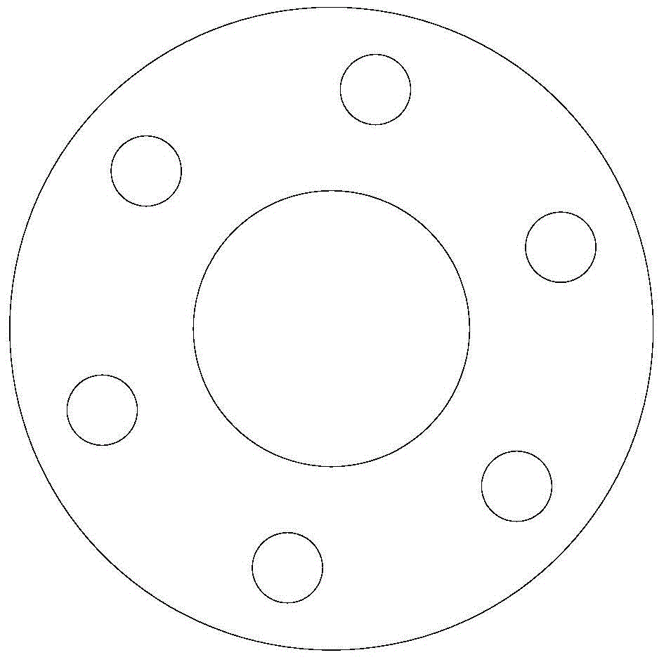
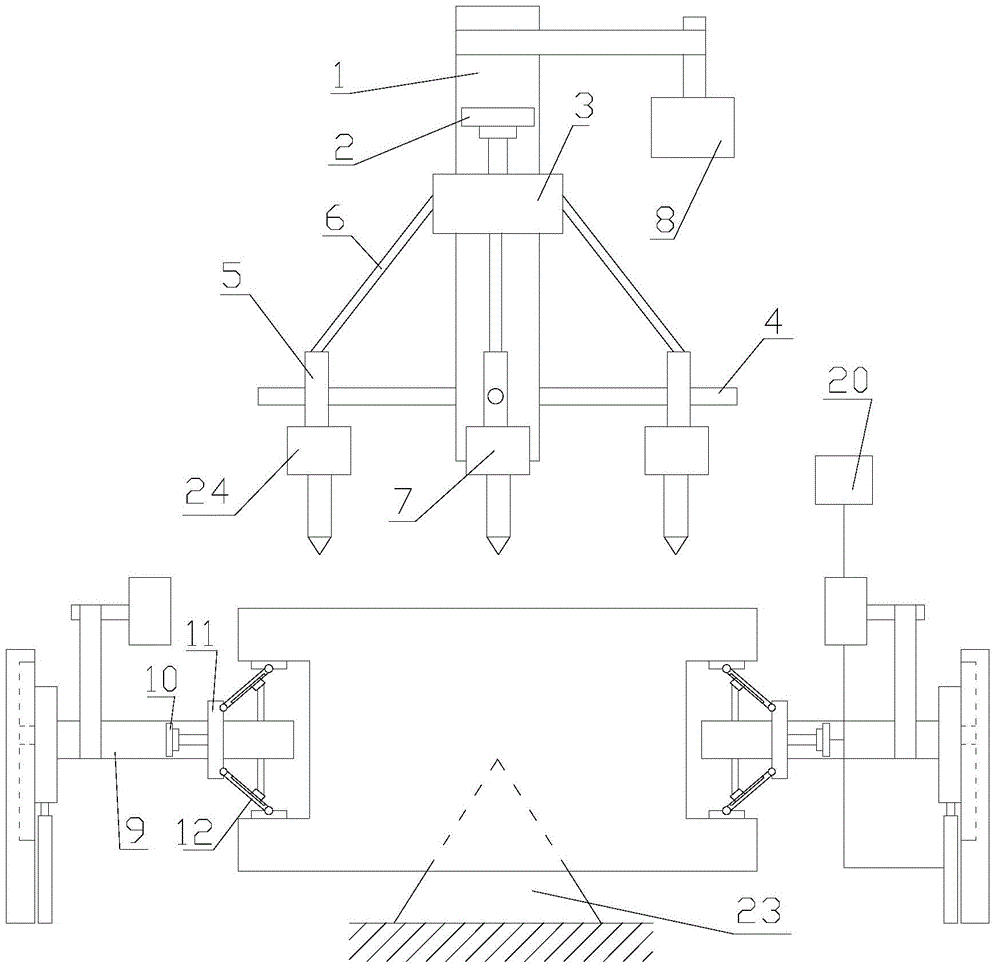
[0034] refer to figure 1 , 2 , 3, 4:

[0035] A device for drilling a flange on a valve proposed by the present invention includes a drilling mechanism for drilling the flange and a clamping mechanism for clamping the valve;

[0036] The drilling mechanism includes a pillar 1 and a hydraulic cylinder 2. The pillar 1 is distributed along the axial direction of the flange. The pillar 1 is provided with a first collar 3 and N slide rods 4, where N is 1, 2, 3, 4 , 5 or 6, the slide bar 4 is distributed around the center of the pillar 1, and the slide bar 4 is arranged parallel to the surface of the flange. When N≠1, the angle between adjacent slide bars 4 is 60 degrees or 180 degrees; N=1 in the present embodiment, the included angle between adjacent slide bar 4 is 60 degree; All be provided with drilling unit on each slide bar 4, this drilling unit passes slide block 5 and slide bar 4 Sliding connection; the first collar 3 is hinged to the sliding block 5 through an equal-leng...


PUM


Abstract

The invention discloses a device for drilling holes in flanges on a valve. The device comprises a drilling mechanism and a clamping mechanism, wherein the drilling mechanism comprises a supporting column and a hydraulic cylinder, the supporting column is distributed along the axial direction of the flanges, a first ferrule and N sliding rods are arranged on the supporting column, N is 1, 2, 3, 4, 5 or 6, the sliding rods are circumferentially distributed by using the supporting column as a center, the sliding rods are arranged in parallel with the surfaces of the flanges, and when N is not equal to 1, an included angle between adjacent sliding rods is 60 or or180 degrees; each sliding rod is provided with a drilling unit, and the drilling unit is slidably connected with the corresponding sliding rod through a sliding block; the first ferrule is hinged to the sliding blocks through the equal-long connecting rods, and the first ferrule is in transmission connection with the hydraulic cylinder; each drilling unit comprises a drill bit and the drilling direction of the drill bit is in parallel with the axial direction of the flanges. The device for drilling holes in the flanges on the valve has the advantages that the processing accuracy is high and the adaptability is good; the sealing performance during connection of the flanges with external pipes is ensured, and the flanges at the two ends of the valve can be automatically drilled.

Description

technical field [0001] The invention relates to the technical field of mining equipment, in particular to a device for drilling holes on an upper flange of a valve. Background technique [0002] A valve is a device used to control the direction, pressure, and flow of a fluid in a fluid system. It is a device that makes or stops the medium in the piping and equipment and controls its flow. [0003] The valve is a control component in the pipeline fluid delivery system. It is used to change the passage section and the flow direction of the medium, and has the functions of diversion, cut-off, throttling, check, diversion or overflow relief. Valves used for fluid control range from the simplest shut-off valve to various valves used in extremely complex automatic control systems. Valves for industrial pipelines. It can be used to control the flow of various types of fluids such as water, steam, oil, gas, mud, various corrosive media, liquid metals and radioactive fluids. The wo...

Claims


Application Information

Patent Timeline
IPC IPC(8): B23B41/00
CPCB23B41/00B23Q3/062B23Q3/08B23Q5/10B23Q5/26
Inventor 倪建平闻斌楠王剑飞
Owner 华东矿用设备有限公司
Why Eureka
Try Eureka