Connected anchor rod and mounting method thereof

A technology of anchor rod and rod body, which is applied in the direction of construction, sheet pile wall, foundation structure engineering, etc., can solve the problems of single force, easy bending and damage, etc., and achieve the effect of convenient installation and operation, avoiding bending damage and shortening the length

Inactive Publication Date: 2015-08-12
GUANGXI UNIV
View PDF5 Cites 1 Cited by
  • Summary
  • Abstract
  • Description
  • Claims
  • Application Information

AI Technical Summary

Problems solved by technology

[0004] The purpose of the present invention is to provide a connecting pipe anchor and its installation method, so as to overcome the shortcomings of the existing anchor, cement mortar and slope with a single and long anchor, which is easy to be bent and damaged during transportation

Method used


Image

  • Connected anchor rod and mounting method thereof

Examples


Embodiment 1

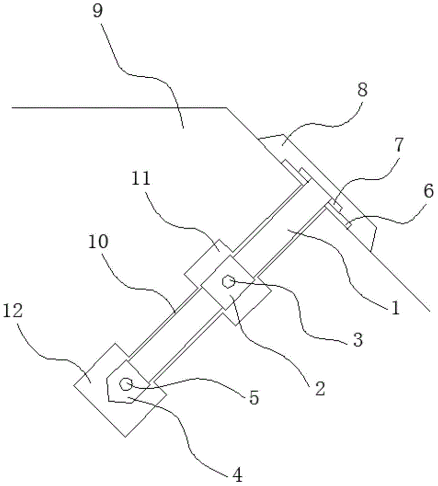
[0028] A takeover type anchor rod, which includes: a rod body 1, a connecting sleeve 2, an anchor head 4, a backing plate 6, and a cover 8, wherein: the rod body 1 is in the shape of a hollow tube with openings at the upper and lower ends, and at least two rod bodies 1 The connection is carried out through the connection sleeve 2 , preferably, the upper and lower ends of the connection sleeve 2 are respectively threaded with the two upper and lower adjacent rod bodies 1 . When it is necessary to install a shorter anchor rod on the slope 9, it can be formed by connecting only two rod bodies 1 through the connecting sleeve 2; They are connected in sequence, and the anchor rod can be split into a plurality of relatively short rod bodies 1 during transportation by forming the anchor rod in the form of connecting pipes, so as to effectively avoid bending damage to the anchor rod during transportation. The diameter of the connecting sleeve 2 is greater than that of the rod body 1, a...

Embodiment 2

[0032] Such as figure 1 Shown, a kind of installation method of above-mentioned takeover type anchor rod, comprises the following steps:

[0033] First, drill the guide hole 10 on the slope 9, the diameter of the guide hole 10 can be greater than the diameter of the anchor head 5 and the connecting sleeve 2, when the diameter of the anchor head 5 and the connecting sleeve 2 are the same, it can ensure that the guide hole 10 The gap between the anchor rod and the whole is relatively uniform.

[0034] Second, the position corresponding to the guide hole 10 and the connecting sleeve 2 on the takeover anchor rod is reamed to form a first chamber 11; and the lower end of the guide hole 10 is reamed to form a second chamber 12.

[0035] Third, assemble several rod bodies 1, connecting sleeves 2 and anchor heads 4, and then insert the assembled whole into the guide hole 10. Since the lower end of the anchor head 4 is pointed, the rod body 1 can be easily and smoothly introduced int...


PUM


Abstract

The invention discloses a connected anchor rod and a mounting method thereof. The connected anchor rod comprises at least two rod bodies, a backing plate, a closing cover and an anchor head, wherein each rod body is of a hollow pipe shape with two open ends, the at least two rod bodies are connected together through a connecting sleeve, the diameter of the connecting sleeve is greater than that of the rod bodies, and at least one first mortar overflowing hole is formed in the middle part of the connecting sleeve; the backing plate sleeves the upper part of the uppermost rod body; the closing cover is connected with the upper end of the uppermost rod body and is used for tightly pressing the backing plate to the surface of a side slope; the anchor head is of a hollow pipe with an open upper end, and the lower end of the anchor head is tipped; the diameter of the anchor head is greater than that of the rod bodies, and the upper end of the anchor head sleeves the lower end of the lowermost rod body; at least one second mortar overflowing hole is formed in the anchor head. According to the connected anchor rod and the mounting method thereof, the structure is simple, the mounting is convenient, the pulling resistance of the anchor rod can be improved, and the rod bodies can be effectively prevented from being subjected bent damage during transportation.

Description

technical field [0001] The invention relates to the field of anchor rods, in particular to a takeover type anchor rod and an installation method thereof. Background technique [0002] A large number of slope projects are involved in the construction of highways, railways and infrastructure in my country. Slope reinforcement is an important part of this project. At present, the reinforcement method widely used is anchor technology. However, due to the existing anchor rods, cement mortar and The force of the slope is relatively simple. Under the long-term external environment, the anchor rod is easy to pull out from the cement mortar, or pull out together with the cement mortar, thus losing the anchoring effect, and the stability and safety of the slope cannot be guaranteed. In addition, longer anchor rods are easily bent and damaged during transportation, resulting in scrapping and increasing anchoring costs. [0003] The information disclosed in this Background section is on...

Claims


Application Information

Patent Timeline
Patent Type & Authority Applications(China)
IPC IPC(8): E02D5/74
Inventor 周晓蓉王明霞黄宏星阎凌云张佳路金文
Owner GUANGXI UNIV
Why Eureka
Try Eureka