Coal mine spontaneous fire fiber temperature detection beam tube monitoring system and method

A technology of bundle tube monitoring and optical fiber temperature measurement, applied in the direction of fire prevention, mining equipment, mining equipment, etc., can solve problems such as difficulty in finding fire sources, economic losses, etc. Effect

Active Publication Date: 2015-08-12
淄博祥龙测控技术有限公司
View PDF9 Cites 25 Cited by
  • Summary
  • Abstract
  • Description
  • Claims
  • Application Information

AI Technical Summary

Problems solved by technology

The mine safety bundle tube monitoring system uses the bundle tube to extract and summarize the air from all parts of the underground to the designated place, and then analyzes the air samples collected by the tube bundle with the help of a chromatographic detection device to realize the detection of CO, CO 2 、CH 4 、C 2 h 4 、C 2 h 6 , O 2 , N 2 On-line monitoring of gas content, the analysis results can be automatically stored in th

Method used


Image

  • Coal mine spontaneous fire fiber temperature detection beam tube monitoring system and method

Examples


Embodiment Construction

[0047] The present invention will be further described below in conjunction with embodiment:

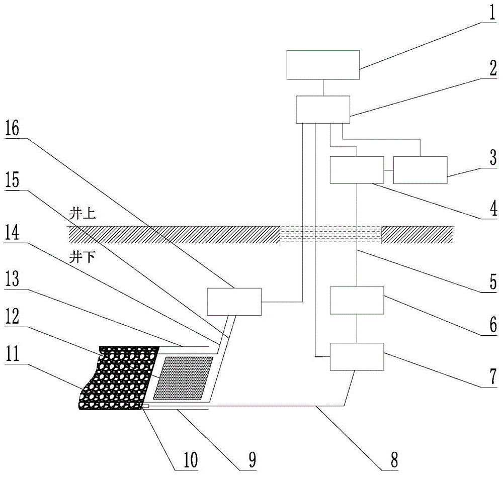
[0048] Such as figure 1 As shown, the coal mine spontaneous combustion fire optical fiber temperature measurement beam tube monitoring system of the present invention includes a beam tube monitoring system, a distributed optical fiber temperature measurement monitoring system and a monitoring and analysis system; the beam tube monitoring system includes a beam tube assembly, and the beam tube assembly is connected with The control cabinets 4 on the well are connected through bundle tubes 5, the control cabinet 4 is connected to the chromatograph 3, and the chromatograph 3 is connected to the alarm device, and the chromatograph 3 is located on the well; Arranged and moved continuously with the advancement of the coal mining face 12, the dust filter 10 is installed at one end of the single pipe 8 located in the return air tunnel 9, and the other end is connected to the gas transmission...


PUM


Abstract

The invention relates to a coal mine spontaneous fire fiber temperature detection beam tube monitoring system and a method, and belongs to the field of coal mine spontaneous fire tendency monitoring and predicting. The coal mine spontaneous fire fiber temperature detection beam tube monitoring system comprises a beam tube monitoring system, distributed fiber temperature detection monitoring systems and a monitoring and analyzing system, wherein the beam tube monitoring system and the distributed fiber temperature detection monitoring systems are respectively connected with the monitoring and analyzing system. The method comprises the following steps: A, the beam tube monitoring system collects underground gas, detects and analyzes gas elements, and transmits data to a monitoring mainframe; B, the monitoring mainframe computes collected gas elements and contents of the collected gas elements according to the data obtained in the step A, and judges fire tendency according to gas element change; C, the distributed fiber temperature detection systems utilize a Raman scattering effect to obtain a temperature change curve of a whole fiber at different positions, and transmit the associated data to the monitoring mainframe; D, the monitoring mainframe receives the data obtained in the step C in real time; E, the monitoring mainframe performs correlation statistic analysis on the data obtained in the step D, determines the fire tendency and determines the position of a fire source point. According to the coal mine spontaneous fire fiber temperature detection beam tube monitoring system and the method, the firing tendency can be judged, and meanwhile, the position of the fire source point can be determined.

Description

technical field [0001] The invention relates to a coal mine spontaneous combustion fire optical fiber temperature measurement beam tube monitoring system and method, belonging to the field of monitoring and forecasting coal mine spontaneous combustion and ignition trends. Background technique [0002] According to statistics, in the coal mines exploited in my country, mines with the risk of spontaneous combustion account for about 70% of the total number of mines, spontaneous combustion coal seams account for 80% of the cumulative mineable coal seams, and the number of spontaneous combustion fires accounts for 10% of the total number of mine fires. More than 94%. Therefore, the prevention of spontaneous combustion accidents must become the focus of coal mine safety research. Timely and accurate early warning of fire, and timely determination of the location of the fire source, not only can timely take fire prevention measures to eliminate fire accidents in the bud, but also ...

Claims


Application Information

Patent Timeline
IPC IPC(8): E21F17/18E21F5/00
CPCE21F5/00E21F17/18
Inventor 白光星胡韶明白念祥
Owner 淄博祥龙测控技术有限公司
Why Eureka
Try Eureka