Single-tank heat storage device with phase change heat storage function and use method thereof

A phase change heat storage and heat storage device technology, which is applied in the direction of heat storage equipment, indirect heat exchangers, heat exchanger types, etc., can solve the problems of not considering the utilization of latent heat, huge heat storage devices, and high system investment and maintenance costs , to achieve the effects of compact structure, stable heat release process and expanded working range

Inactive Publication Date: 2015-08-12
BEIJING UNIV OF TECH
View PDF11 Cites 21 Cited by
  • Summary
  • Abstract
  • Description
  • Claims
  • Application Information

AI Technical Summary

Problems solved by technology

[0003] At present, the relatively mature heat storage method for high-temperature solar heat utilization is double-tank sensible heat storage, the heat storage device is huge, and the system investment and maintenance costs are high. In order to reduce the heat storage cost, the applicant's patents ZL201420140252. A single-tank energy storage device and a single-tank electric energy storage device store solar thermal energy or electric energy in the form of sensible heat in a single tank, and then use an immersion heat exchanger to realize the storage and release of heat energy. Thermal system saves cost and saves space
However, this patent only realizes sensible heat storage, and does not take into account latent heat utilization. In order to improve heat storage efficiency, the present invention proposes a heat storage device with phase change heat storage, which realizes both sensible heat storage and latent heat storage. hot

Method used


Image

  • Single-tank heat storage device with phase change heat storage function and use method thereof
  • Single-tank heat storage device with phase change heat storage function and use method thereof
  • Single-tank heat storage device with phase change heat storage function and use method thereof

Examples


Embodiment 1

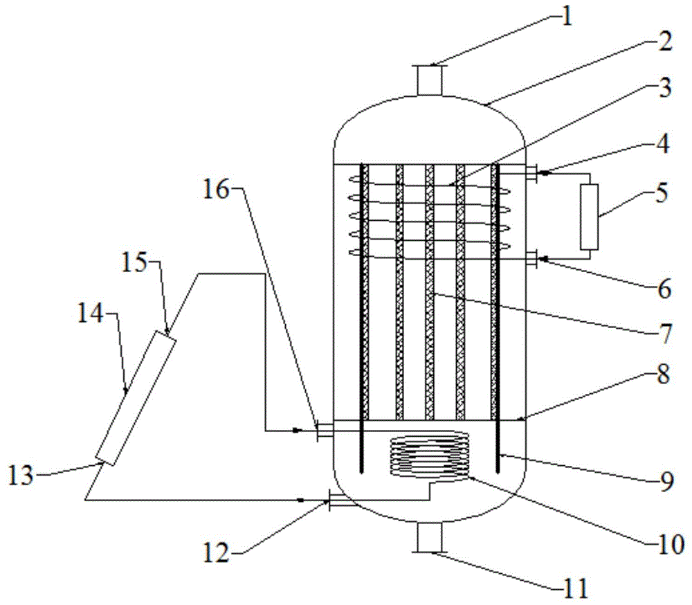
[0039] Example 1, such as Figure 1-4 As shown, a single-tank heat storage device with phase change heat storage described in the first embodiment of the present invention includes:

[0040] The single-tank regenerator 2 has a heat storage medium inlet 1 on the top outside and a heat storage medium outlet 11 on the bottom outside;

[0041] Heat insulation plate 9, which is arranged inside the single-tank heat accumulator 2 and arranged coaxially with the single-tank heat accumulator 2;

[0042] The phase change heat storage device 7 is arranged inside the heat insulation plate 9 and fixed inside the single tank heat accumulator 2 through the tube sheet 8, and the phase change heat storage device 7 is filled with a phase change heat storage medium;

[0043] The exothermic coil heat exchanger 3 is arranged on the upper part of the annular channel formed by the heat insulation plate 9 and the single-tank heat accumulator 2. The medium inlet 6 is connected to the exothermic medi...

Embodiment 2

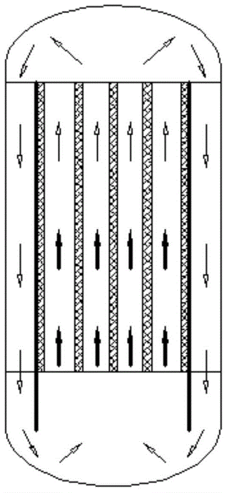
[0057] Example 2, such as Figure 5 As shown, the single-tank heat storage device with phase change heat storage described in the second embodiment of the present invention is similar to Embodiment 1, the difference is that:

[0058] The heat transfer medium and the heat storage medium are the same medium, and the heat storage coil heat exchanger 10 at the inner bottom of the single-tank heat accumulator 2 is omitted. Tank accumulator 2. The heat transfer medium outlet 12 and the heat transfer medium inlet 16 are omitted, and the heat transfer medium from the solar heat collector 14 enters the single-tank heat accumulator 2 from the heat storage medium inlet 1, and pushes the low-temperature medium in the single-tank heat accumulator 2 to It moves downward, flows out from the heat storage medium outlet 11 at the bottom, and then enters the solar heat collector 14 for heating.

Embodiment 3

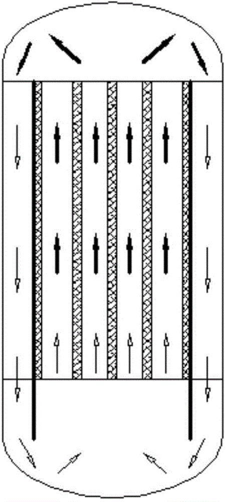
[0059] Example 3, such as Figure 6 As shown, the single-tank heat storage device with phase change heat storage described in the third embodiment of the present invention is similar to Embodiment 2, the difference is that:

[0060] The size of the phase-change heat storage device 7 is reduced, and a coil electric heater 17 is installed at the bottom of the single-tank heat accumulator 2, and a power supply device 19 is added outside the single-tank heat accumulator 2, and the coil electric heating The device 17 is connected to the power supply equipment 19 through the inlet 18 of the electric heating equipment. When the solar thermal energy stored by the solar heat collector 14 is insufficient during the day, the coil electric heater 17 can be used for electric heating at night to realize the heat storage process.


PUM


Abstract

The invention discloses a single-tank heat storage device with a phase change heat storage function. The single-tank heat storage device with the phase change heat storage function comprises a single-tank heat reservoir, heat insulation boards, a phase change heat storage device, a heat release coil heat exchanger, a heat supply device and a heat transferring device, wherein the outer top of the single-tank heat reservoir is provided with a heat storage medium inlet; the outer bottom of the single-tank heat reservoir is provided with a heat storage medium outlet; the heat insulation boards are arranged inside the single-tank heat reservoir and are coaxial with the single-tank heat reservoir; the phase change heat storage device is arranged in the heat insulation boards, fixed inside the single-tank heat reservoir through a tube plate and filled with phase change heat storage media; the heat release coil heat exchanger is arranged on the upper portion of an annular channel formed by the heat insulation boards and the single-tank heat reservoir; an outlet and an inlet of the heat release coil heat exchanger are connected with a heating medium inlet and a heating medium outlet of an energy utilization device respectively; the heat supply device is arranged outside the single-tank heat reservoir; the heat transferring device is arranged at the bottom in the single-tank heat reservoir and connected with the heat supply device. The single-tank heat storage device with the additional phase change heat storage function has the advantages that the structure is simple, the heat storage capacity is increased, the heat release process is stable, and the working temperature range is wide.

Description

technical field [0001] The invention relates to the technical field of heat storage energy utilization, in particular to a single-tank heat storage device with phase change heat storage and a method for using the same. Background technique [0002] Chai Jing's "Under the Dome" is a strong tipping point of the "energy-life" problem, and the smog problem caused by energy consumption has once again focused people's attention. If the adjustment of the energy structure is not carried out, the smog problem will be difficult to solve, and it will even restrict the economic development of our country. Therefore, the development of renewable energy has gradually become a national policy of our country. Energy storage is a key link in the large-scale utilization of renewable energy. Energy storage can improve the efficiency of high-temperature solar heat utilization, improve the current problem of wind power and photovoltaic power generation that are difficult to connect to the grid,...

Claims


Application Information

Patent Timeline
Patent Type & Authority Applications(China)
IPC IPC(8): F28D20/00
CPCY02E60/14Y02E70/30
Inventor 鹿院卫李小丽吴玉庭马重芳
Owner BEIJING UNIV OF TECH
Why Eureka
Try Eureka