
Support mounting and detecting mechanism

A detection mechanism and mounting plate technology, applied in the direction of measuring devices, connecting components, mechanical equipment, etc., can solve the problems of low work efficiency, slow speed, easy fatigue of workers, etc., to improve work efficiency, accurate detection position, and reduce labor intensity. Effect

Active Publication Date: 2015-08-12
BOZHON PRECISION IND TECH CO LTD
View PDF7 Cites 0 Cited by
  • Summary
  • Abstract
  • Description
  • Claims
  • Application Information

AI Technical Summary

Problems solved by technology

[0003] (1) It is inconvenient to pick up and install with small tweezers, the speed is slow, the keys and gaskets are easy to fall off, the workers are prone to fatigue, and the work efficiency is low
[0004] (2) When using small tweezers to pick up the button and put it into the mounting hole, it is easy to cause the center of the button to deviate from the mounting hole
[0005] (3) The thickness of the gasket filled between the button and the button bracket is not suitable, which affects the effect of the button

Method used


Image

  • Support mounting and detecting mechanism
  • Support mounting and detecting mechanism
  • Support mounting and detecting mechanism

Examples


Embodiment Construction

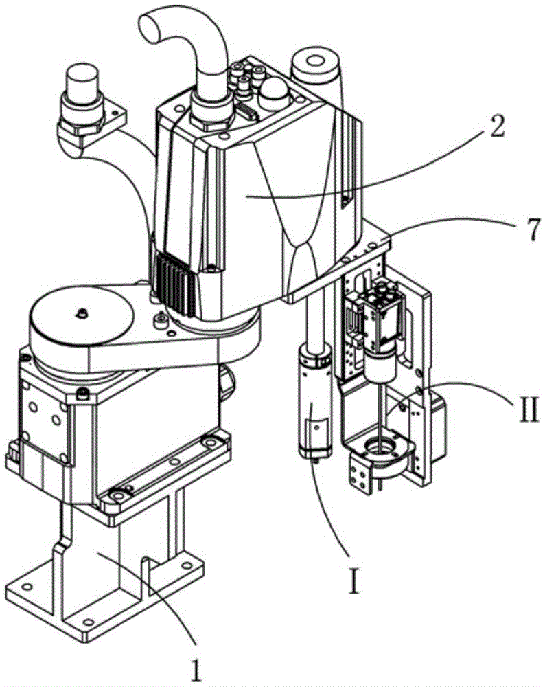
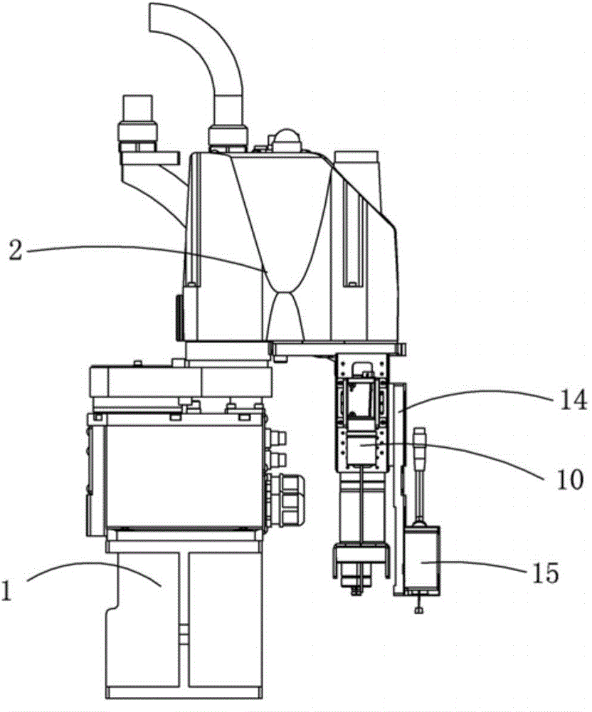
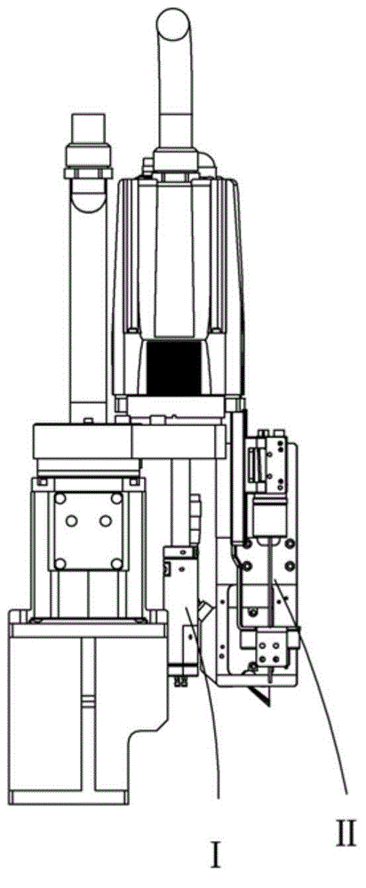
[0024] Examples, see attached Figure 1~5 , a bracket installation and detection mechanism, a manipulator base 1 is screwed and fixedly installed with a manipulator 2, and the lower end of the manipulator is respectively equipped with a manipulator R-axis mechanism I and a manipulator CCD laser mechanism II, and the manipulator R-axis mechanism includes an R-axis connecting block 3. R-axis clamping block 4, R-axis suction nozzle fixing block 5 and R-axis suction nozzle 6, the R-axis connecting block is installed at the lower end of the rotating shaft of the manipulator, and the R-axis connecting block is clamped by the R-axis clamping block It is fixed at the lower end of the rotating shaft; the lower end of the R-axis connecting block is connected with the R-axis nozzle fixing block, and the lower end of the R-axis nozzle fixing block is connected with the R-axis nozzle; there are two R-axis nozzles, which are symmetrically installed on the R-axis The lower end of the nozzle ...


PUM


Abstract

The invention relates to a support mounting and detecting mechanism. A manipulator base is provided with a manipulator, and the lower end of the manipulator is respectively provided with a manipulator R shaft mechanism and a manipulator CCD laser mechanism. A R shaft connecting block of the manipulator R shaft mechanism is disposed at the lower end of a rotating shaft of the manipulator, and is clamped and fixed through a R shaft clamping block. The lower end of the R shaft connecting block is connected to a R shaft nozzle through a R shaft nozzle fixing block. The front side of the lower part of an upper CCD mounting plate of the manipulator CCD laser mechanism is provided with an upper fixing vertical plate, and the front side of the upper fixing vertical plate is provided with an upper CCD through an upper CCD fixed plate. The back part of the upper fixing vertical plate is provided with a circular light source through an upper circular light source mount. The right side of the upper fixing vertical plate is provided with an upper laser through an upper laser fixed plate. The support mounting and detecting mechanism is advantageous in that a support can be installed and the mounting device can be detected; the height difference between the two step surfaces of the support can be measured; a pad can be conveniently applied to the support; pad selection can be ensured to be accurate, and the applying position of the pad can be guaranteed to be precise.

Description

Technical field: [0001] The invention relates to the field of installation and detection mechanism equipment, and more specifically relates to a bracket installation and detection mechanism. Background technique: [0002] In the manufacturing process of electronic products, such as mobile phones, it is necessary to assemble buttons to the electronic products. In some small-scale factories, the assembly of the buttons of electronic products depends on the workers to use small tweezers to pick up the buttons and place them in the corresponding housing mounting holes, and then the workers use the tweezers to pick up the small gaskets of the buttons and place them in the corresponding holes. The center of the button, and finally the button bracket is locked to the product with screws, and the button is fixed to the product from the back. Assembling buttons has the following disadvantages like this: [0003] (1) It is inconvenient to pick up and install with tweezers, the speed...

Claims


Application Information

Patent Timeline
Patent Type & Authority Applications(China)
IPC IPC(8): G01B11/02G01B11/00F16B11/00
Inventor 吕绍林汪炉生李忠夏俊明占枝武
Owner BOZHON PRECISION IND TECH CO LTD
Learn More