Micro accelerometer with fbar structure on diaphragm

A micro-accelerometer and diaphragm technology, applied in the direction of acceleration measurement using inertial force, can solve the problems of small cross-coupling between modes, increase the mechanical strength of the device, etc., and achieve small cross-coupling, high mechanical strength and high sensitivity Effect

Inactive Publication Date: 2017-12-22
INST OF ELECTRONICS ENG CHINA ACAD OF ENG PHYSICS
View PDF2 Cites 0 Cited by
  • Summary
  • Abstract
  • Description
  • Claims
  • Application Information

AI Technical Summary

Problems solved by technology

[0007] In order to solve the above-mentioned technical defects, the present invention provides a micro-accelerometer with FBAR structure on a diaphragm. The micro-accelerometer with this structure has high sensitivity (Δf / a is on the order of 100kHz / g), low power consumption (FBAR It has the advantages of low power consumption), high reliability (avoiding various complex mechanical / electrical failure modes in micromechanical resonators), good manufacturability (no fine movable structures with complex motion forms in micromechanical resonators, CMOS Process compatible and easy monolithic integration), high operating frequency (f0 is in the order of GHz), can also improve the influence of temperature on FBAR sensitivity, increase the mechanical strength of the device, the distribution of leads is no longer limited by the beam width, and the first-order mode The mode frequency is far from other orders, the cross-coupling between modes is small, and the mass block and elastic diaphragm can be formed by using a relatively simple back-cavity etching process; the micro-accelerometer with FBAR structure on the diaphragm may meet the requirements of Target detection, recognition and control systems require medium-to-high-precision, high-stability micro-accelerometers

Method used


Image

  • Micro accelerometer with fbar structure on diaphragm
  • Micro accelerometer with fbar structure on diaphragm
  • Micro accelerometer with fbar structure on diaphragm

Examples


Embodiment Construction

[0037] The present invention is described in detail below in conjunction with accompanying drawing:

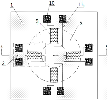
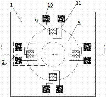
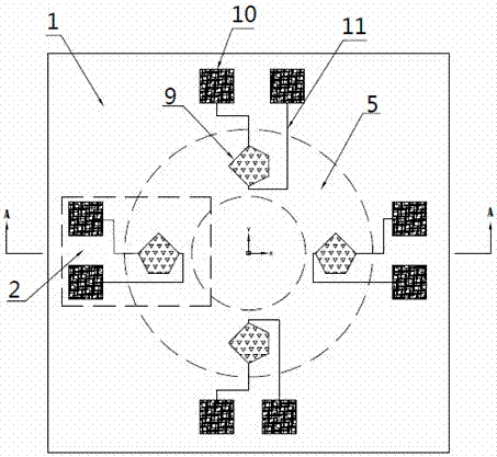
[0038] Such as Figure 1(a)-1(e) , 2 are respectively a top view structure schematic diagram and a top view structure schematic diagram in the present invention.

[0039] A micro-accelerometer with FBAR structure on the diaphragm, including an inertial force-sensitive structure, a detection element 2 and a composite film 1, the composite film 1 is used to connect the inertial force-sensitive structure and the detection element 2, and the inertial force-sensing structure is located below the composite film 1, The detection element 2 is located above the composite film 1; the inertial force sensitive structure includes a Si mass block 4, a Si base 3 and a cavity 6; the Si mass block 4 is arranged in the central area of ​​the bottom of the composite film 1, and the Si base 3 is annular Set in the edge area of ​​the bottom of the composite film 1, a cavity 6 is formed between the ...


PUM


Abstract

The invention discloses a micro accelerometer with an FBAR structure on a diaphragm, comprising an inertial force sensitive structure, a detection element and a composite film, the composite film is used to connect the inertial force sensitive structure and the detection element, the inertial force sensitive structure is located below the composite film, and the detection The element is located above the composite film; the inertial force sensitive structure includes a Si mass block, a Si base and a cavity; the Si mass block is arranged in the central area of ​​the bottom of the composite film, and the Si base is arranged in a ring shape at the edge area of ​​the bottom of the composite film. There is a cavity between the Si mass, the Si base and the composite film, that is, the Si base surrounds the Si mass, the Si mass and the Si base are separated by the cavity, and the corresponding composite film on the Si mass and the cavity is The elastic diaphragm area; the detection element includes FBAR, leads, and pads, and the FBAR is connected to the pads through leads; the invention has the advantages of good manufacturability, high temperature stability, small cross-coupling between modes, and high mechanical strength.

Description

technical field [0001] The invention belongs to the field of micro-electro-mechanical system devices, in particular to a micro-accelerometer with a FBAR (film bulk acoustic-wave resonators) structure on a diaphragm. The micro-accelerometer with this structure has high rigidity and a Small cross-coupling between them, high sensitivity and good linearity. technical background [0002] Micro accelerometer is one of the most important MEMS sensors. At present, it mainly uses detection principles such as capacitance, piezoresistive, and field effect transistors. The meter outputs a weak analog signal, which is easily affected by factors such as ambient temperature, parasitic capacitance, and electromagnetic interference. It is difficult to meet the requirements of medium and high precision inertial measurement. The output frequency of the resonant micro accelerometer based on the micromechanical resonator is a quasi-digital signal, which has the advantages of strong anti-interfe...

Claims


Application Information

Patent Timeline
Patent Type & Authority Patents(China)
IPC IPC(8): G01P15/09
Inventor 高杨何婉婧李君儒贺学峰蔡洵赵俊武尹汐漾黄振华
Owner INST OF ELECTRONICS ENG CHINA ACAD OF ENG PHYSICS
Why Eureka
Try Eureka