Magnetic recording head and disk device with the same

A magnetic recording head and recording layer technology, applied in the direction of magnetic recording head, magnetic recording, recording head casing/shield, etc., can solve the problem that the high-frequency oscillator is difficult to achieve favorable oscillation

Active Publication Date: 2015-08-12
KK TOSHIBA
View PDF6 Cites 74 Cited by
  • Summary
  • Abstract
  • Description
  • Claims
  • Application Information

AI Technical Summary

Problems solved by technology

However, when the magnetic field applied to the recording medium from the recording gap of the magnetic core is strong, the magnetic field inside the recording gap is too strong, making it difficult for the favorable oscillation of the high-frequency oscillator to be achieved.

Method used


Image

  • Magnetic recording head and disk device with the same
  • Magnetic recording head and disk device with the same
  • Magnetic recording head and disk device with the same

Examples


no. 1 example

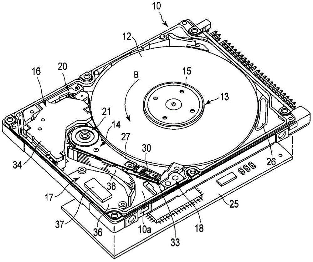
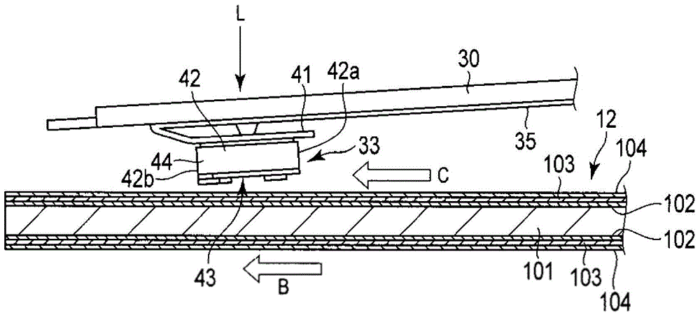
[0022] figure 1 shows the internal structure of the HDD with the top cover removed according to the first embodiment, and figure 2 Shows the head in a floating state. Such as figure 1 As shown in , the HDD includes a housing 10. The housing 10 includes a base 10a having the shape of an open-top rectangular box and a top cover (not shown) in the shape of a rectangular plate. The top cover is attached to the base by a plurality of screws to close the top opening of the base. Thus, the housing 10 remains sealed inside and is ventilated to the outside only through the breather filter 26 .

[0023] On the base portion 10a, there are provided a magnetic disk 12 as a recording medium in the form of a disk and a mechanical part. The mechanical part includes: a spindle motor 13 which supports and rotates the magnetic disk 12; a plurality of magnetic heads 33, such as two, which record and read information to and from the magnetic disk 12; A magnetic head 33 is movably supported;...

no. 2 example

[0067] Figure 9 It is a front view of the distal end portion of the magnetic recording head in the HDD according to the second embodiment viewed from the main magnetic pole 60 side. According to this embodiment, the second protrusion 72 forming the magnetic portion is formed in a trapezoidal shape whose shape in the track width direction conforms to the shape of the tapered portion 60 a of the main magnetic pole 60 . The lower end of the second protrusion 72 on the ABS 43 side is in contact with the front-side end surface 62 b of the tail shield 62 . Even when a magnetic portion having such a shape is used, the high-frequency oscillator can be in a good oscillation state and the error rate is improved.

no. 3 example

[0069] Figure 10 is a sectional view along the track center showing the distal end portion of the magnetic recording head in the HDD according to the third embodiment. According to this embodiment, the second protrusion 72 forming the magnetic portion is formed to protrude more toward the main magnetic pole 60 than the first protrusion 70 extends toward the main magnetic pole 60 . Here, the main magnetic pole 60 side of the protruding end of the second protrusion 72 is positioned without being aligned with the oscillation layer 65 c of the spin torque oscillator 65 . In contrast, the second protrusion 72 is positioned between a plane (substantially perpendicular to the recording layer of the recording medium) in which the oscillation layer 65c is provided and the front-side end surface 62b.

[0070] According to the magnetic recording head configuration described above, the magnetic field applied to the spin torque oscillator 65 within the write gap can be further reduced; t...


PUM

PropertyMeasurementUnit
diameteraaaaaaaaaa

Abstract

A magnetic recording head includes a main magnetic pole that generates a recording magnetic field in a direction perpendicular to a recording layer, a write shield with a surface that faces a trailing side of the main magnetic pole, so that a write gap is interposed between the surface and the main magnetic pole, the write shield forming a magnetic core together with the main magnetic pole, a recording coil, a high frequency oscillator within the write gap, a wiring through which a current can flow through the main magnetic pole, the high frequency oscillator, and the write shield in series, and a magnetic element made of soft magnetic material, positioned within the write gap and separated from the high frequency oscillator, and configured to form a magnetic path passing through the main magnetic pole, the magnetic element, and the write shield, and not through the high frequency oscillator.

Description

[0001] Cross References to Related Applications [0002] This application is based on and claims the benefit of priority from Japanese Patent Application No. 2014-22279 filed on February 7, 2014, the entire contents of which are incorporated herein by reference. technical field [0003] Embodiments described herein relate generally to magnetic recording heads and disk devices having such heads. Background technique [0004] Recently, magnetic heads for perpendicular magnetic recording have been proposed to increase the recording density and capacity of magnetic disk devices, or to reduce the size thereof. In this magnetic head, the recording head includes a main magnetic pole for generating a vertical magnetic field, a write shield magnetic pole arranged on a trailing side of the main magnetic pole with a write gap interposed therebetween, and a magnetic flux is fed to the main magnetic pole. circle. Further, a high-frequency assist head has been proposed in which a high-f...

Claims


Application Information

Patent Timeline
Patent Type & Authority Applications(China)
IPC IPC(8): G11B5/23G11B5/11G11B5/31
CPCG11B5/17G11B5/35G11B5/11G11B5/1278G11B5/3146G11B2005/0024
Inventor 田口知子
Owner KK TOSHIBA
Why Eureka
Try Eureka