Power amplifier and implementation method thereof

A technology for power amplifiers and power amplifier chips, which is applied in power amplifiers, improved amplifiers to increase efficiency, improved amplifiers to reduce noise effects, etc., to achieve the effects of eliminating high-order harmonics, high linearity, and improved linearity

Inactive Publication Date: 2015-08-12
HANGZHOU DIANZI UNIV
View PDF3 Cites 4 Cited by
  • Summary
  • Abstract
  • Description
  • Claims
  • Application Information

AI Technical Summary

Problems solved by technology

[0005] The purpose of the present invention is to address the vacancies of the prior art, based on the defect that the high-efficiency power amplifier has a higher output of the second harmonic and the third harmonic, so that its linearity decreases, and proposes a frequency division positive feedback high linearity A new type of power amplifier circuit with high efficiency, through the recycling of harmonics, the amplifier can have high linearity while having high efficiency

Method used


Image

  • Power amplifier and implementation method thereof

Examples


Embodiment Construction

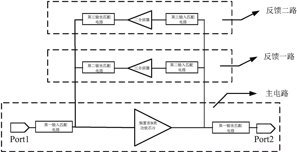
[0019] Such as figure 1 As shown, a power amplifier includes a main circuit, a feedback circuit and a feedback circuit;

[0020] The main circuit includes a first input matching circuit, a first output matching circuit and a biased class B power amplifier chip; one feedback circuit includes a second input matching circuit, a second output matching circuit and a three-frequency divider; the second feedback circuit includes a third input matching circuit, a third output matching circuit and a frequency divider by two;

[0021] The input end of the first input matching circuit is connected to the input signal end, the output end of the first input matching circuit is biased at the radio frequency signal input end of the class B power amplifier chip, the output end of the second output matching circuit, and the third output The output end of the matching circuit is connected, and the output end of the class B power amplifier chip is biased to connect with the input end of the fir...


PUM


Abstract

The invention discloses a power amplifier and an implementation method thereof. The power amplifier comprises a main circuit, a first feedback circuit and a second feedback circuit; the main circuit comprises a first input matching circuit, a first output matching circuit and a power amplifier chip biased on the B class; the first feedback circuit comprises a second input matching circuit, a second output matching circuit and a three-way frequency divider; the second feedback circuit comprises a third input matching circuit, a third output matching circuit and a two-way frequency divider. According to the power amplifier and the implementation method thereof, the input end and the output end of the power amplifier chip biased on the B class are connected with the two-way frequency divider and the three-way frequency divider respectively to form the two regenerative feedback circuits, and therefore second harmonics and third harmonics in a power amplifier chip output signal can pass through the frequency dividers respectively to be converted into fundamental harmonics and then fed back to the input end of the chip; higher harmonics in the output signal are eliminated, the high linearity is improved, and the power amplifier biased on the B class enables the circuits to have higher efficiency.

Description

field of invention [0001] The invention relates to a microwave power amplifying circuit, specifically a power amplifier and its realization method. technical background [0002] The power amplifier is the core component of the RF front-end equipment. The performance of the power amplifier, especially the linearity and efficiency, has a direct impact on the RF front-end equipment such as base stations and repeaters. The better the linearity of the power amplifier, the higher the output power of the system when the power amplifier is applied to the radio frequency system, otherwise, the lower the output power of the system; like other radio frequency modules, the higher the efficiency of the power amplifier, the better. That is to say, on the one hand, it is hoped that the power amplifier can achieve very high output power, and at the same time, it must have high efficiency. However, due to the inherent internal contradictions of traditional power amplifiers: when outputting ...

Claims


Application Information

Patent Timeline
IPC IPC(8): H03F1/02H03F1/26H03F1/32H03F3/20
Inventor 程知群颜国国朱丹丹陈帅王凯范凯凯
Owner HANGZHOU DIANZI UNIV
Why Eureka
Try Eureka