
An accessory mount

A technology for mounting seats and accessories, which is applied to agricultural machinery and implements, applications, agricultural machinery, etc. It can solve problems such as large cantilever beam force, large damage to the rotary tiller, deformation of the cantilever beam or chassis frame, etc., and achieves easy replacement , Reduce maintenance costs and improve maintenance efficiency

Active Publication Date: 2018-05-08
XINGGUANG AGRI MACHINERY
View PDF7 Cites 0 Cited by
  • Summary
  • Abstract
  • Description
  • Claims
  • Application Information

AI Technical Summary

Problems solved by technology

[0003] In the prior art, the cantilever beam of front-end operation accessories such as bulldozing blades is often directly connected to the chassis frame through bolts and other fixing methods. During the tillage process of the rotary tiller, if there are such When obstacles with high resistance such as large rocks are used, due to their large force on the cantilever beam, it is easy to cause deformation of the cantilever beam or the chassis frame, or deformation of the bolts at the connection position between the cantilever beam and the chassis frame. Come, it will cause great damage to the rotary tiller as a whole, and it is not easy to maintain

Method used


Image

  • An accessory mount
  • An accessory mount
  • An accessory mount

Examples


Embodiment 1

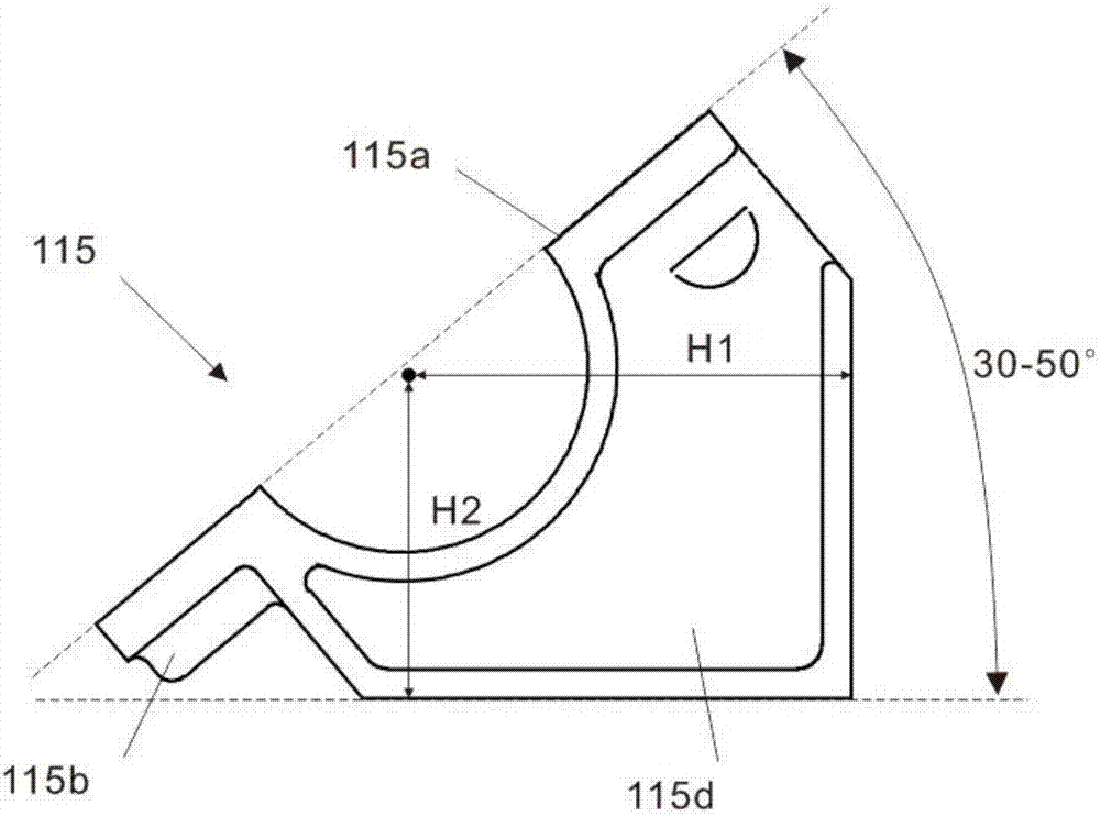
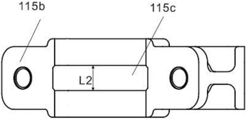
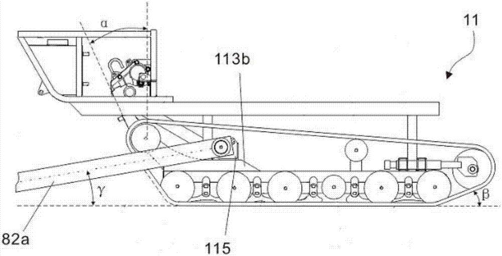
[0021] An accessory mounting seat, which is made of cast iron and has an integral structure, the accessory mounting seat 115 has a mounting surface 115a, the mounting surface 115a is inclined relative to the horizontal plane, and the inclination angle is 40°, the front end of the mounting surface 115a and the rear The end is a lug-shaped mounting ear 115b, and the center of the mounting ear 115b is provided with a bolt hole, and is fastened to the bolt hole of the left and right heightening beams 113b of the chassis frame 11 through bolts. On the top, the bottom of the mounting surface 115a is a base 115d along its longitudinal axis and perpendicular to the mounting surface 115a. The mounting surface 115a also has a semi-cylindrical opening whose center line is consistent with its transverse axis direction. The center line of the semi-cylindrical opening is The distance H1=12cm to the rear end face of the base, the distance H2=9cm from the center line of the semicylindrical ope...

Embodiment 2

[0024] The second embodiment of the present invention is improved on the basis of the first embodiment, and its main difference from the embodiment is that the installation surface 115a is inclined relative to the horizontal plane, the inclination angle is 35°, and the width L2 of the groove 115c = 4cm, the width of the semi-cylindrical opening = 14cm, it also includes a matching upper cover, the lower surface of the upper cover also has a semi-cylindrical opening, and can cooperate with the semi-cylindrical opening on the mounting surface 115a , forming a closed cylinder, the surface of the semi-cylindrical opening of the upper cover is provided with a concentric semicircular groove, the width of the groove is the same as the width L2 of the groove 115c of the accessory mount 115, the base The bottom surface of 115d is parallel to the ground, and the distance between it and the ground is 35cm. In order to make the angle γ≤8° between the accessory cantilever beam 82a and the gr...


PUM


Abstract

The invention relates to an accessory mounting seat, which has an integrated structure and has a mounting surface (115a), the front end and the rear end of the mounting surface (115a) are lug-shaped mounting ears (115b), and the mounting ears ( 115b) is provided with a bolt hole at the center, the bottom of the mounting surface (115a) is a base (115d) along its longitudinal axis and perpendicular to the mounting surface (115a), and the mounting surface (115a) also has a central line and its transverse A semi-cylindrical opening with the same axis direction. With the accessory mounting seat of the present invention, the front accessories are installed on the accessory mounting seat, and the accessory mounting seat is installed on the chassis frame. The front accessories and the chassis frame avoid direct connection, because the yield limit of the accessory mounting seat is lower than that of the cantilever Even if the beam and chassis frame encounter obstacles with high resistance, it will not cause damage and deformation of the cantilever beam or chassis frame. Moreover, the accessory mounting base is detachably connected to the chassis frame, and the replacement is also very simple, greatly improving Improve maintenance efficiency and reduce maintenance costs.

Description

technical field [0001] The invention relates to a connection structure between an accessory and a frame, in particular to an accessory mounting seat. Background technique [0002] In the field of agricultural machinery, such as crawler-type rotary cultivators, the rotary cultivating implements are generally mounted on the back of the chassis frame. In order to improve farming efficiency, accessories, such as bulldozing blades, are often mounted on the front of the chassis frame. [0003] In the prior art, the cantilever beam of front-end operation accessories such as bulldozing blades is often directly connected to the chassis frame through bolts and other fixing methods. During the tillage process of the rotary tiller, if there are such When obstacles with high resistance such as large rocks are used, due to their large force on the cantilever beam, it is easy to cause deformation of the cantilever beam or the chassis frame, or deformation of the bolts at the connection pos...

Claims


Application Information

Patent Timeline
Patent Type & Authority Patents(China)
IPC IPC(8): A01B59/00
Inventor 朱云飞顾伟施健
Owner XINGGUANG AGRI MACHINERY
Learn More