Mixed jet generation method and drainage structure thereof

A technology of jet flow and fluid flow rate, which is applied in the direction of mixing methods, mixers, fluid mixers, etc., can solve the problems of large water consumption, incomplete decontamination, and slow decontamination speed of decontamination nozzles, so as to improve the decontamination effect , high versatility, and the effect of increasing water volume

Inactive Publication Date: 2015-08-19
汪勇
View PDF5 Cites 3 Cited by
  • Summary
  • Abstract
  • Description
  • Claims
  • Application Information

AI Technical Summary

Problems solved by technology

[0006] The technical problem to be solved by the present invention is: to overcome the technical problems of large water consumption, slow decontamination speed, and incomplete decontamination of the deco

Method used


Image

  • Mixed jet generation method and drainage structure thereof
  • Mixed jet generation method and drainage structure thereof

Examples


Embodiment 1

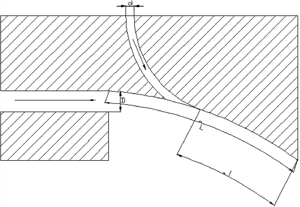
[0041] Such as figure 1 As shown, this structure is a jet drainage structure including a liquid medium flow guide and a gas medium flow guide, mainly including the air flow nozzle, the decontamination liquid nozzle and the confluence arc surface, the arc of the confluence arc surface is 35°, the arc The length is L, the radius is R, the air flow nozzle (jet port of B medium guide piece) is located at one end of the confluence arc surface, and the decontamination liquid nozzle (A medium guide piece jet port) on the confluence arc surface, decontamination The arc length between the liquid nozzle and the air nozzle is l;

[0042] The gap width of the airflow spout (jet outlet of medium guide member B) is D, and the gap width of the decontamination nozzle (jet outlet of medium guide member A) is d, where D is greater than d;

[0043] The air flow nozzle includes an upper surface and a lower surface. The upper surface is connected to the confluence arc surface through an arc surfa...

Embodiment 2

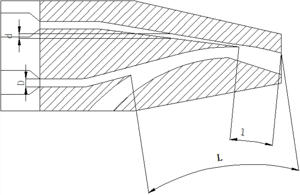
[0048] Such as figure 2 As shown, this structure includes a nozzle main body, and two parallel connecting pipes are arranged at the tail of the nozzle main body. A flow pipe, wherein the liquid flow medium guide pipe is located at the upper part of the air flow medium guide pipe, and a main flow channel is also arranged at the lower part of the air flow medium guide pipe and the liquid flow medium guide pipe;

[0049] The main flow channel is formed by two arc-shaped surfaces C at intervals. Between the two arc-shaped surfaces C is the main flow guide channel. The main flow guide channel mainly includes a drainage section and a confluence section. The outlet of the medium diversion pipe is located on the diversion section, and the high-pressure fluid ejected from the air medium diversion pipe and the liquid flow medium diversion pipe converge at the confluence section, wherein the width of the confluence section is much larger than that of the diversion section;

[0050] The...

Embodiment 3

[0056] Changing the flow rate of the gas medium fluid and the liquid medium fluid by changing the working load of the gas medium fluid and the liquid medium fluid driving the pump;

[0057] By adjusting the flow rate of the gas medium fluid to be A, wherein because the diameter of the air flow nozzle is constant, there is a linear relationship between the flow rate and the flow rate;

[0058] By adjusting the liquid medium fluid, the flow rate is B, wherein because the diameter of the liquid flow nozzle is also constant, there is a linear relationship between the flow rate and the flow rate;

[0059] At this time, adjusting the mixing relationship between A and B can obtain mixed jets in different states.

[0060] 1. Adjust A so that A is greater than 0, and B is adjusted to be equal to 0. At the same time, A must meet the resistance along the surface of the confluence arc surface. At this time, a thin surface-shaped gas fluid of pure gas will be obtained, which can be mainly ...


PUM

PropertyMeasurementUnit
Radianaaaaaaaaaa

Abstract

The invention relates to a mixed jet generation method and a drainage structure thereof. The structure comprises an A medium flow guiding member, a B medium flow guiding member and a conflux cambered surface; the jet axis of each of the A medium flow guiding member and the B medium flow guiding member is tangent to the conflux cambered surface; and the tail end of the conflux cambered surface is provided with a jet end, the total length from the jet end to the cambered surface of the jet port of the A medium flow guiding member is l, the total length from the jet end to the cambered surface of the jet port of the B medium flow guiding member is L, and L is greater than l. The method is characterized in that the direction of jet direction of the A medium flow guiding member along the conflux cambered surface is same to the movement direction of a decontamination solution nozzle along the conflux cambered surface, the decontamination solution is driven under high speed airflow and is jetted along an optimized curve to form a thin layer water curtain or curtain-shaped water droplets, and different decontamination effects can be reached by adjusting the mixing ratio of gas and liquid in order to realize high application degree.

Description

technical field [0001] The invention relates to a method for generating mixed jets and a drainage structure thereof, belonging to the field of decontamination equipment. Background technique [0002] According to the relevant requirements of the latest "Guidelines for the Research of Logistics Science and Technology of the Whole Army (2014-2017)", design a system that meets the major needs of medical support when encountering biological, chemical or nuclear weapons attacks, or related unexpected emergencies, especially The decontamination equipment meets the needs of economical and efficient decontamination when encountering biological, chemical and nuclear weapons attacks or accidents in the case of water shortage in field battles, tunnel operations, long-term voyages of ships (especially submarines), etc. One of the major security issues of concern; [0003] At present, the conventional three-proof decontamination uses water guns and sprayers to spray flowering jets or mi...

Claims


Application Information

Patent Timeline
IPC IPC(8): B01F3/04B01F5/20
Inventor 汪勇闵晓
Owner 汪勇
Why Eureka
Try Eureka