
A device for opening wire grooves on the wall of a building

A technology for building walls and surface lines, applied in stone processing equipment, other manufacturing equipment/tools, work accessories, etc., can solve the problems of affecting the wire arrangement, low efficiency of manual knocking, affecting construction efficiency, etc., to ensure the grinding effect. , the effect of promoting the opening efficiency and improving the opening efficiency

Active Publication Date: 2020-12-22
CHANGXIN CONSTR CO LTD
View PDF12 Cites 0 Cited by
  • Summary
  • Abstract
  • Description
  • Claims
  • Application Information

AI Technical Summary

Problems solved by technology

[0003] a: The depth of the wire groove on the wall is not uniform, which leads to the inconsistent depth of the wire groove cutting, which affects the arrangement of the wire rods in the later stage, and further affects the installation effect of the wire rods; b: After the wire groove is opened, it is necessary to manually tap the bottom of the wire groove. The knocking efficiency is low, and manual knocking is difficult to keep the bottom end of the wire groove level; it affects the arrangement of the wires in the later stage, causing the unevenness of the wires arranged inside the wire grooves to affect the overall wire arrangement effect; it makes it difficult for workers to install the wires; affects the construction efficiency

Method used


Image

  • A device for opening wire grooves on the wall of a building
  • A device for opening wire grooves on the wall of a building
  • A device for opening wire grooves on the wall of a building

Examples


Embodiment Construction

[0022] Embodiments of the present invention will be described below with reference to the drawings. In the process, in order to ensure the clarity and convenience of illustration, we may exaggerate the width of the lines or the size of the constituent elements in the diagram.

[0023] In addition, the following terms are defined based on the functions in the present invention, and may be different according to the user's or operator's intention or practice. Therefore, these terms are defined based on the entire content of this specification.

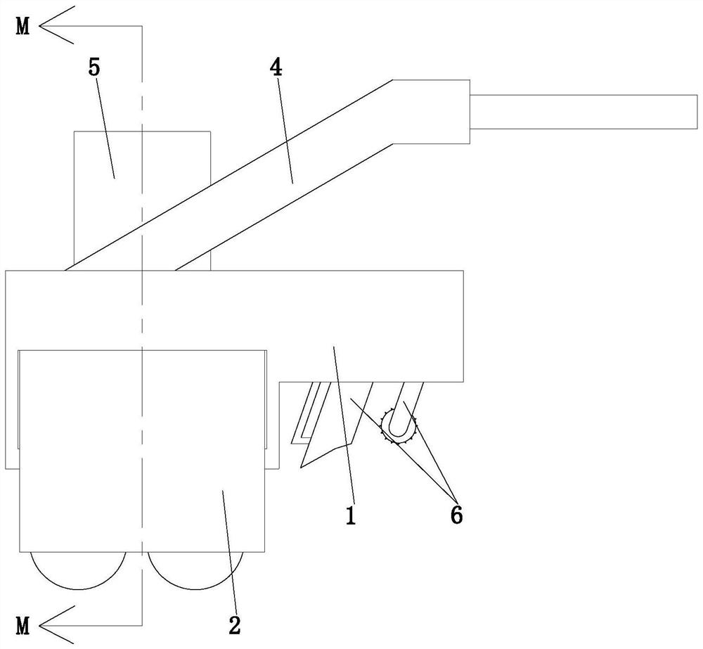
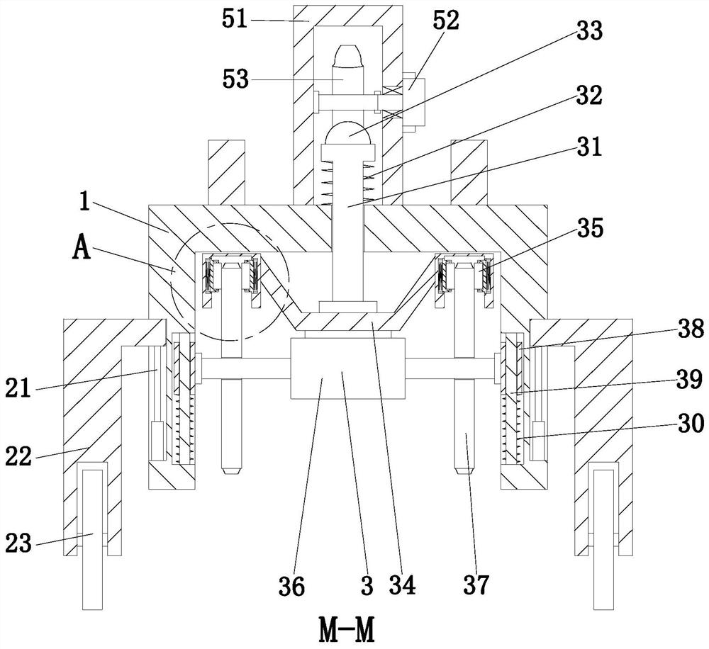
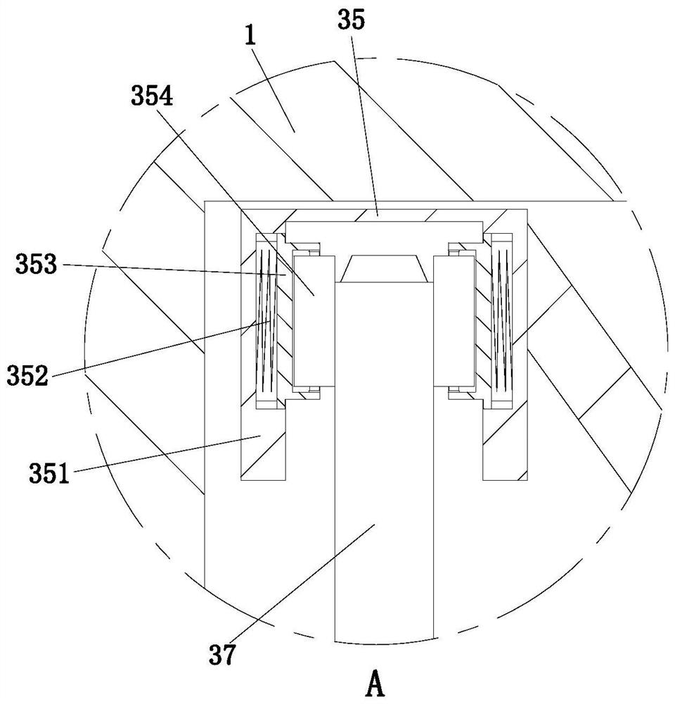
[0024] like Figure 1 to Figure 4 As shown, a device for opening wire grooves on the wall surface of a house construction includes a U-shaped frame 1, an auxiliary device 2, a cutting device 3, a handle 4, a driving device 5 and an executing device 6; the front and rear ends of the U-shaped frame 1 An auxiliary device 2 is arranged symmetrically on the outer wall, a cutting device 3 is arranged at the inner left side of the U-shaped fr...


PUM


Abstract

Provided is a house building wall line groove forming apparatus, comprising a U-shaped frame, an auxiliary apparatus, a cutting apparatus, a handle, a drive apparatus, and an execution apparatus. Thepresent invention can solve main problems of a traditional wall line groove cutter in the use process: a. the inconsistent cutting depths of line grooves caused by the nonuniform forming depths of thewall line grooves influences the later arrangement of lines, and further influences the line mounting effect; and b. the manual beating of the bottom ends of the line grooves is needed after formation of the line grooves, the manual beating efficiency is lower, and it is difficult to maintain the levelness of the bottom ends of the line grooves by the manual beating, so that the later arrangementof the lines is influenced, the whole line arrangement effect is influenced by the unevenness of the lines arranged in the line grooves, and the problems such as difficult manual mounting of the lines and influence on the construction efficiency are generated.

Description

technical field [0001] The invention relates to the technical field of building construction, in particular to a device for opening wire grooves on the wall surface of a house building. Background technique [0002] The wiring trough, also known as the wiring trough, the wiring trough, and the wiring trough, is used to arrange and fix the wire specifications such as power lines and data lines inside the wall; the opening of the wall wiring trough needs to be done by a wall cutting machine. Cutting and slotting, but the current wall slotting machine mainly has the following problems in the process of use: [0003] a: The depth of the wire groove on the wall is not uniform, which leads to the inconsistent depth of the wire groove cutting, which affects the arrangement of the wire rods in the later stage, and further affects the installation effect of the wire rods; b: After the wire groove is opened, it is necessary to manually tap the bottom of the wire groove. The knocking ...

Claims


Application Information

Patent Timeline
Patent Type & Authority Patents(China)
IPC IPC(8): B28D1/24B28D1/26B28D7/00B24B3/60
CPCB24B3/60B28D1/24B28D1/26B28D7/00
Inventor 杨正伟史永波胡考
Owner CHANGXIN CONSTR CO LTD
Learn More