Press machine with damping function

A press and functional technology, applied in the field of presses, can solve the problems of poor stamping quality, poor shock absorption performance, and low work efficiency of workpieces, and achieve the effects of improving shock absorption performance, enhancing strength, and prolonging service life

Inactive Publication Date: 2017-12-22
WUHU QIANKAI MATERIAL TECH CO LTD
View PDF6 Cites 0 Cited by
  • Summary
  • Abstract
  • Description
  • Claims
  • Application Information

AI Technical Summary

Problems solved by technology

[0003] The object of the present invention is to provide a machine with reasonable structure design, high work efficiency, good stamping stability, and reduction in pressure, aiming at the problems of inconvenient operation, low work efficiency, poor shock absorption performance and low stamping quality of the workpiece existing in the existing press. A press with shock absorption function that has good shock performance and high workpiece stamping quality

Method used


Image

  • Press machine with damping function
  • Press machine with damping function
  • Press machine with damping function

Examples


Embodiment 1

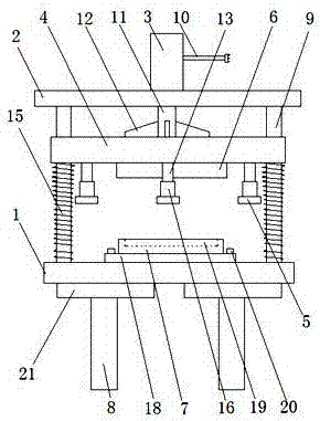
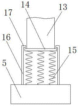
[0020] as attached Figure 1-3 As shown, a press with shock absorbing function includes an operating table 1, a fixed plate 2, a cylinder 3, a slider 4, a limit block 5, an upper pressing block 6 and a lower pad 7, and is characterized in that: The console 1 is set on the support 8, the column 9 is set on the console 1, the fixed plate 2 is set on the column 9, the cylinder 3 is set on the fixed plate 2, and the cylinder 3 is set Piston rod 11, power cord 10 are arranged, described slide block 4 is arranged on the column 9, slide block 4 is connected with piston rod 11, and connecting rod 13 is arranged on slide block 4, described stop block 5 A connecting sleeve 16 is arranged on the connecting sleeve 16, and a limit ring 17 is arranged on the connecting sleeve 16, and the connecting sleeve 16 is connected with the connecting rod 13. The upper pressing block 6 is arranged on the slider 4, and the lower pressing block 6 is arranged on the sliding block 4. The pad 7 is provide...

Embodiment 2

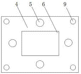
[0028] as attached Figure 4 As shown, a press with shock absorbing function includes an operating table 1, a fixed plate 2, a cylinder 3, a slider 4, a limit block 5, an upper pressing block 6 and a lower pad 7, and is characterized in that: The console 1 is set on the support 8, the column 9 is set on the console 1, the fixed plate 2 is set on the column 9, the cylinder 3 is set on the fixed plate 2, and the cylinder 3 is set Piston rod 11, power cord 10 are arranged, described slide block 4 is arranged on the column 9, slide block 4 is connected with piston rod 11, and connecting rod 13 is arranged on slide block 4, described stop block 5 A connecting sleeve 16 is arranged on the connecting sleeve 16, and a limit ring 17 is arranged on the connecting sleeve 16, and the connecting sleeve 16 is connected with the connecting rod 13. The upper pressing block 6 is arranged on the slider 4, and the lower pressing block 6 is arranged on the sliding block 4. The pad 7 is provided ...


PUM


Abstract

The invention discloses a press machine with a damping function. The press machine comprises a control console, a fixed plate, an air cylinder, a sliding block, limiting blocks, an upper pressing block and a lower cushion block. The press machine is characterized in that the control console is arranged on supports, the fixed plate is arranged on stand columns, the air cylinder is arranged on the fixed plate, the sliding block is arranged on the stand columns, and connecting sleeves are arranged on the limiting blocks; and the upper pressing block is arranged on the sliding block, a mounting plate and a bearing groove are formed in the lower cushion block, and the mounting plate is arranged on the control console through mounting bolts. According to the press machine with the damping function, springs are arranged on the stand columns between the sliding block and the control console, the impact force of the sliding block driving the upper pressing block to descend can be reduced through the springs, the impact strength of the upper pressing block to a workpiece can be maintained, and the service life of the press machine can further be prolonged; and reinforcing blocks are arranged between the control console and the supports, the connecting strength between the control console and the supports can be improved through the reinforcing blocks, the strength of the press machine is enhanced, and further the damping property of the press machine is enhanced.

Description

technical field [0001] The invention relates to the technical field of presses, in particular to a press with a shock absorbing function. Background technique [0002] The press is a kind of production equipment commonly used in metal stamping and forming. During the stamping process of the workpiece by the press, due to the increased impact force of the press, it will not only cause waste workpieces, but also cause damage to the press. For example, the patent application number 201710306418.9 discloses a metal stamping device with partial pressure and shock absorption, which solves the problem that the base of the press is under heavy force and is easily damaged, but it has the disadvantages of inconvenient operation, low work efficiency, and poor shock absorption performance. Good, the workpiece stamping quality is not high. Contents of the invention [0003] The purpose of the present invention is to provide a reasonable structural design, high working efficiency, good...

Claims


Application Information

Patent Timeline
Patent Type & Authority Applications(China)
IPC IPC(8): B21D22/02F16F15/04
CPCB21D22/02F16F15/04
Inventor 卢国孝吕昊丁祖琴
Owner WUHU QIANKAI MATERIAL TECH CO LTD
Why Eureka
Try Eureka