power pack driven clip

A technology of power components and clips, applied in metal processing and other directions, to achieve the effect of small size, reduced load, and compact structure

Active Publication Date: 2017-10-03
杨志强
View PDF6 Cites 0 Cited by
  • Summary
  • Abstract
  • Description
  • Claims
  • Application Information

AI Technical Summary

Problems solved by technology

Its structure usually includes two clamping parts, and the workpiece is clamped or released by the two clamping parts approaching or moving away from each other. In the automatic production line using clamps, it is usually necessary to automatically control the approaching or away, however there is no such clip in the prior art

Method used


Image

  • power pack driven clip
  • power pack driven clip

Examples


Embodiment 1

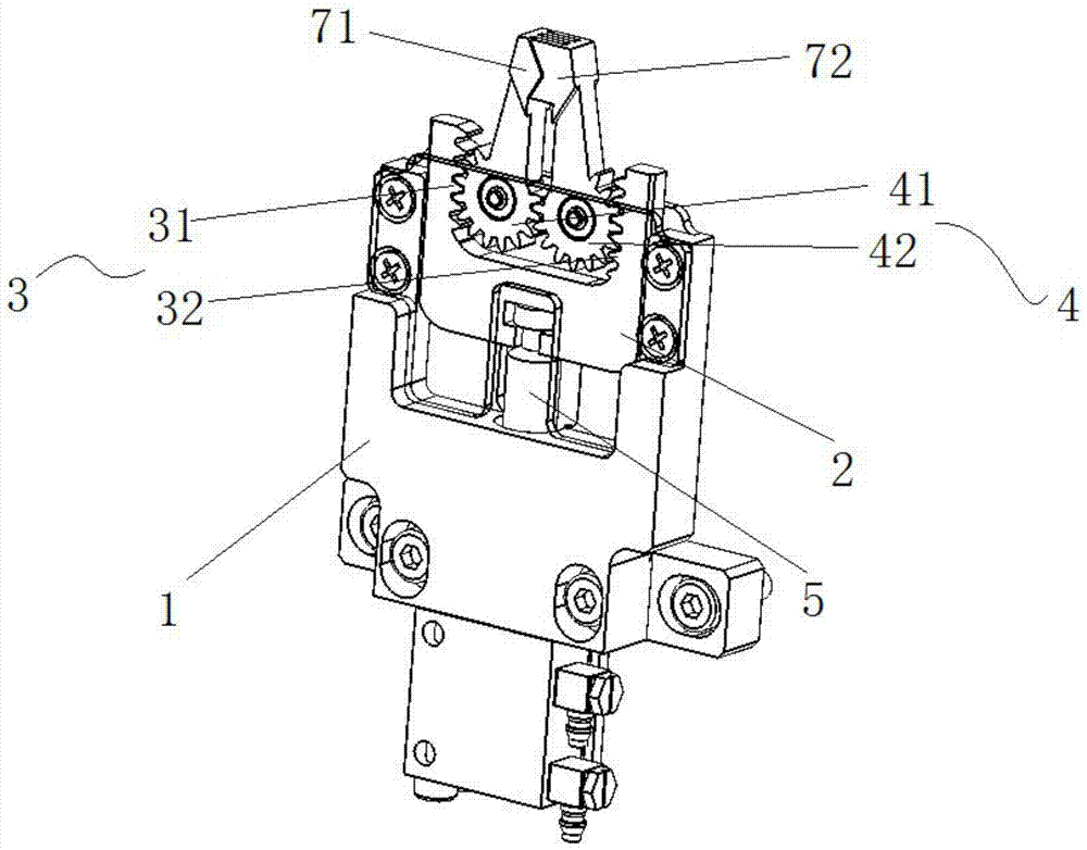
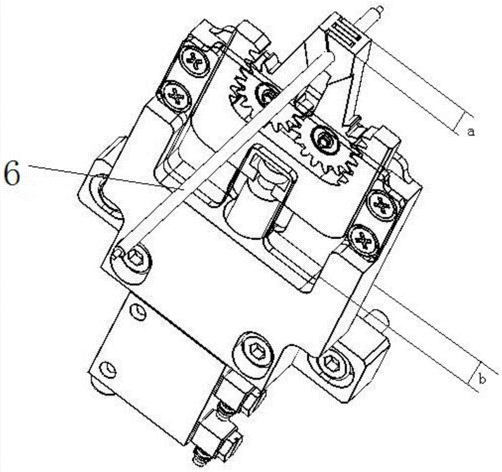
[0028] Such as Figure 1-Figure 2 As shown, a clamp driven by a power assembly includes a base 1, a clamping arm and a power assembly, one end of the clamping arm is rotatably connected to the base 1, and the other end of the clamping arm is provided with a 6, the clamping action of the workpiece 6 is realized by the closeness of at least two clamping parts, so the number of clamping arms is at least two; the power assembly drives the clamping arms to rotate through the transmission mechanism, so that The clamping parts on different clamping arms are brought together or separated.

[0029] The power unit drives the power assembly through the transmission mechanism, thereby driving the clamping arm to rotate, so that the clamping parts on different clamping arms are relatively close or separated, thereby realizing clamping or releasing the workpiece 6, the control end of the power unit and the automatic production line The control unit (such as PLC) is connected by communicati...

Embodiment 2

[0038] The difference between this embodiment and Embodiment 1 is that the forms of the power assembly and the transmission mechanism are as follows: a chute is provided on the base 1, and the power assembly includes a slider, a connecting rod and a crank. It is slidably installed in the slot, one end of the connecting rod is rotatably connected to the slider, the other end of the connecting rod is rotatably connected to the crank, and the crank is eccentrically fixedly connected to the rotating connection end of the clamping arm; the number of power components is two. The power output end of the power unit is connected to the slider, which drives the slider to reciprocate along the chute, so that the connecting rod drives the crank to move in a circle, and finally drives the clamping arm to rotate. The rotation angle can be determined by the travel switch set on the base 1 To control, the limit switch is used to detect the position of the clamping part, and the limit switch is...

Embodiment 3

[0040] The difference between this embodiment and Embodiment 1 is that the forms of the power assembly and the transmission mechanism are as follows: the power assembly includes two worms that are rotatably connected to the base 1, and the two worms are respectively the first worm and the second worm. Worm, the rotating connection ends of the two clamping arms are fixedly connected with a worm gear, the two worm gears are respectively the first worm gear and the second worm gear, the first worm is matched with the first worm gear, and the second worm is matched with the second worm gear . The power unit drives the first worm and the second worm to rotate directly or through the transmission mechanism, respectively making the first worm wheel and the second worm wheel rotate, thereby driving the two clamping arms to rotate, and the angle of rotation can also be adjusted by setting the base The limit switch on the seat 1 is controlled by the limit switch, which is used to detect...


PUM


Abstract

The invention discloses a power assembly driven clamp comprising a base, at least two clamping arms and a power assembly. One end of every clamping arm is rotatably connected to the base, and the other end of each clamping arm is provided with a clamping part used for clamping a workpiece. The power assembly drives the clamping arms to rotate through a transmission mechanism, thus the different clamping parts of the clamping arms are closed or separated. The clamp has the advantages that a power unit drives the power assembly through the transmission mechanism so that the clamping arms are driven to rotate, the different clamping parts of the clamping arms are relatively closed or separated so as to clamp or release the workpiece, the control end of the power unit is in communication connection with a control unit (PLC (programmable logic controller) of an automatic production line, and the clamp is controlled to clamp or release the workpiece though controlling the operating state of the power unit.

Description

technical field [0001] The invention relates to a device for clamping workpieces, in particular to a clamp driven by a power assembly. Background technique [0002] Clamps, usually used to clamp workpieces. Its structure usually includes two clamping parts, and the workpiece is clamped or released by the two clamping parts approaching or moving away from each other. In the automatic production line using clamps, it is usually necessary to automatically control the approaching or Far away, however, there is no such a clip in the prior art. Contents of the invention [0003] The purpose of the present invention is to provide a clamp driven by a power unit. The power unit drives the power unit through a transmission mechanism, thereby driving the clamping arm to rotate, so that the clamping parts on different clamping arms are relatively close or separated, thereby realizing clamping. To tighten or release the workpiece, the control end of the power unit communicates with t...

Claims


Application Information

Patent Timeline
Patent Type & Authority Patents(China)
IPC IPC(8): B23Q7/04
CPCB23Q7/043B23Q7/046
Inventor 杨志强
Owner 杨志强
Why Eureka
Try Eureka