
Vehicle working mode switching method and system of hybrid electric vehicle and transmission control unit

A vehicle controller and hybrid vehicle technology, applied in hybrid vehicles, motor vehicles, transportation and packaging, etc., can solve problems such as long mode switching time, reduced system reliability, and large clutch wear, so as to shorten power interruption Time, reduce wear, avoid the effect of frustration

Active Publication Date: 2015-08-19
BEIQI FOTON MOTOR CO LTD
View PDF6 Cites 24 Cited by
  • Summary
  • Abstract
  • Description
  • Claims
  • Application Information

AI Technical Summary

Problems solved by technology

[0004] The disadvantages of the existing vehicle working mode switching method are: 1) there is no active speed regulation process of the engine and the ISG motor before the clutch is combined, and the mode switching time is too long; Synchronization will produce a lot of frustration, and the driving experience is poor; 3) The clutch is worn out and the reliability of the system is reduced

Method used


Image

  • Vehicle working mode switching method and system of hybrid electric vehicle and transmission control unit
  • Vehicle working mode switching method and system of hybrid electric vehicle and transmission control unit
  • Vehicle working mode switching method and system of hybrid electric vehicle and transmission control unit

Examples


Embodiment 1

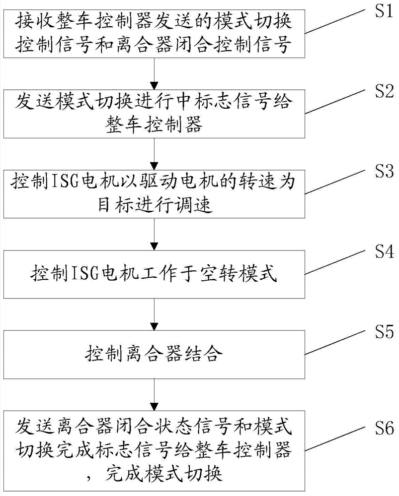
[0066] Such as figure 2 As shown, the present embodiment provides a method for switching the working mode of a hybrid vehicle for a gearbox controller, including the following steps:

[0067] S1: The current working mode of the vehicle is the series mode. When it needs to switch to the parallel mode, it receives the mode switching control signal and the clutch closing control signal sent by the vehicle controller;

[0068] S2: Take over the control right, and send the mode switching in progress flag signal to the vehicle controller;

[0069] S3: Control the automobile starter generator integrated motor to work in the speed control mode, and adjust the speed of the automobile starter generator integrated motor with the speed of the driving motor as the target speed;

[0070] S4: After the integrated motor of the automobile starter and generator completes the speed regulation, control the integrated motor of the automobile starter and generator to work in the idling mode;

[...

Embodiment 2

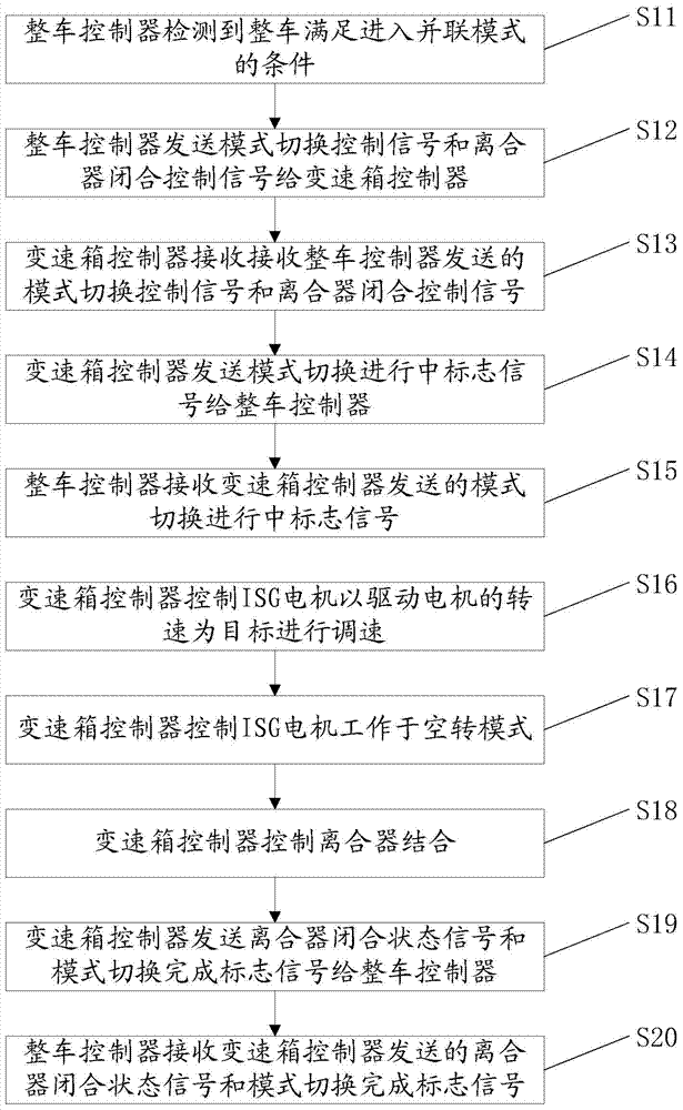
[0079] Such as image 3 As shown, this embodiment provides a method for switching the working mode of a hybrid vehicle, which is used in a vehicle controller and a gearbox controller, including the following steps:

[0080] S11: The current working mode of the vehicle is the series mode. When the vehicle controller detects that the vehicle meets the conditions for entering the parallel mode, the desired mode of the vehicle changes to the parallel mode.

[0081] S12: The vehicle controller sends a mode switching control signal and a clutch closing control signal to the gearbox controller, and also sends a mode switching control signal to the gearbox controller.

[0082] S13: The gearbox controller receives the mode switching control signal and the clutch closing control signal sent by the vehicle controller.

[0083] S14: The gearbox controller takes over the control right, and sends a signal indicating that the mode switching is in progress to the vehicle controller.

[0084...

Embodiment 3

[0096] Such as Figure 4 As shown, it is a timing diagram during the process of switching the working mode of the hybrid vehicle from the series mode to the parallel mode, including the following process:

[0097] Before time T1, the current working mode of the whole vehicle is the series mode, the ISG motor works in the speed control mode, the engine works in the torque control mode, and the gearbox controller controls the clutch to be in the disengaged state.

[0098] At time T1, the vehicle controller judges that the vehicle satisfies the conditions for driving in the parallel mode, and the desired mode of the vehicle changes to the parallel mode. The vehicle controller sends the mode switching control signal and the clutch closing control signal to the gearbox controller, and the gearbox controller takes over the control of the system, and sends the mode switching in progress flag signal to the vehicle controller.

[0099] From time T1 to time T2, the gearbox controller c...


PUM


Abstract

The invention provides a vehicle working mode switching method and a vehicle working mode switching system of a hybrid electric vehicle. The method comprises the steps of receiving a mode switching control signal and a clutch closing control signal sent by a vehicle controller when the vehicle is required to be switched to a parallel mode from a series mode; sending a mode switching in-progress marking signal to the vehicle controller; controlling an ISG motor to work in a rotation speed control mode, and adjusting the speed of the ISG motor by taking the rotation speed of a drive motor as the target; controlling the ISG motor to work in an idle mode; controlling the clutch to be combined; sending a clutch closed state signal to the vehicle controller. The vehicle working mode switching method and the vehicle working mode switching system of the hybrid electric vehicle have the advantages that the technical problems of long interruption time of power and great wear of the clutch in mode switching caused by a fact that rotation speeds of the ISG motor and the drive motor are synchronized through a sliding membrane of the clutch in mode switching of the existing hybrid electric vehicle are solved, and the active speed adjusting process of the ISG motor and the drive motor is added before the clutch is combined, so that the mode switching time is shortened and the smoothness in the process of mode switching is improved.

Description

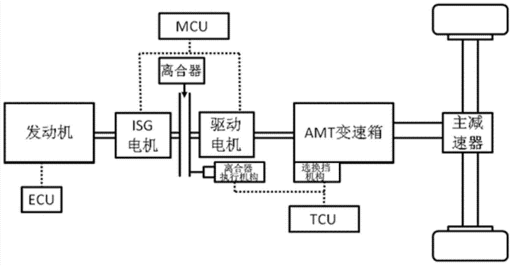
technical field [0001] The invention relates to the technical field of vehicle control. Specifically, it relates to a method and a system for switching working modes of a hybrid electric vehicle. Background technique [0002] Such as figure 1 As shown, the structure of the existing vehicle hybrid power system, the solid line indicates the mechanical connection, and the dotted line indicates the connection relationship of the control signal, including the engine, clutch, clutch actuator, automobile starter generator (ISG motor), drive motor, AMT Gearbox and final drive. The hybrid power system is a dual-motor single-clutch mode, and the control system is complicated, but it can realize the switching of various working modes such as pure electric, series, parallel, start-stop, etc. [0003] In the structure of the above-mentioned hybrid power system, the switching of the working mode of the whole vehicle is one of the key technologies. In the existing working mode switchin...

Claims


Application Information

Patent Timeline
Patent Type & Authority Applications(China)
IPC IPC(8): B60W10/02B60W10/08B60W10/06B60W30/182B60W20/00
CPCB60W10/02B60W10/08B60W20/20B60W2710/021B60W2710/081Y02T10/62
Inventor 苗壮孔令安
Owner BEIQI FOTON MOTOR CO LTD
Learn More