Pay-off device

A technology of pay-off device and mounting frame, which is applied in the direction of transportation and packaging, delivery of filamentous materials, thin material processing, etc. It can solve the problems of easily scratching human hands and waste of resources, so as to avoid scratches, avoid waste, short length effect

Inactive Publication Date: 2015-08-19
国网山东济南市历城区供电公司 +1
View PDF6 Cites 10 Cited by
  • Summary
  • Abstract
  • Description
  • Claims
  • Application Information

AI Technical Summary

Problems solved by technology

[0003] The purpose of the present invention is to provide a wire pay-off device, which is used to solve the problems of waste of resources and scratches on hands when straightening hard wires with bare hands.

Method used


Image

  • Pay-off device
  • Pay-off device
  • Pay-off device

Examples


Embodiment Construction

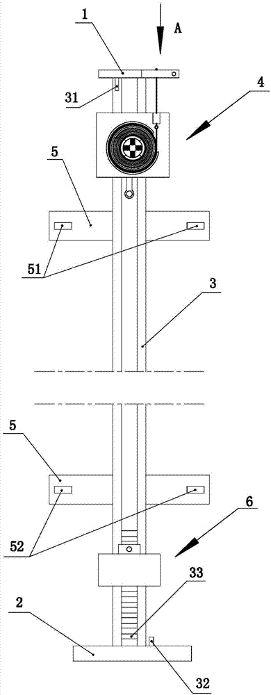
[0026] Such as Figure 1 to Figure 9 Shown, the present invention mainly comprises front fixed plate 1, rear fixed plate 2, guide rail 3, walking assembly 4, mounting plate 5, straightening assembly 6, clamping assembly and thread gripper 8, below in conjunction with accompanying drawing to this The invention is described in detail.

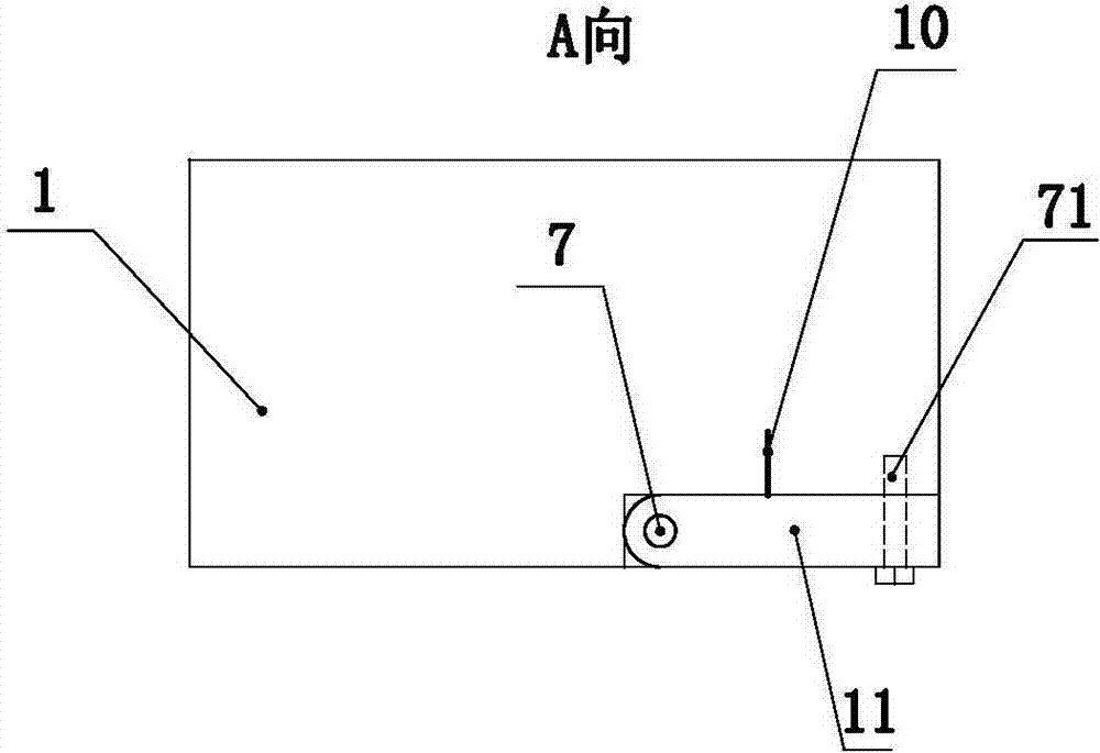
[0027] Such as figure 1 As shown, the front fixed plate 1 and the rear fixed plate 2 are respectively vertically fixed on the ground, and the distance between the front and rear fixed plates is tens of meters or even more than one hundred meters, which is greater than the total length of hard wires in a wire reel. length. A pair of guide rails 3 are arranged between the front fixed plate and the rear fixed plate, and a walking assembly 4 is arranged on the guide rails.

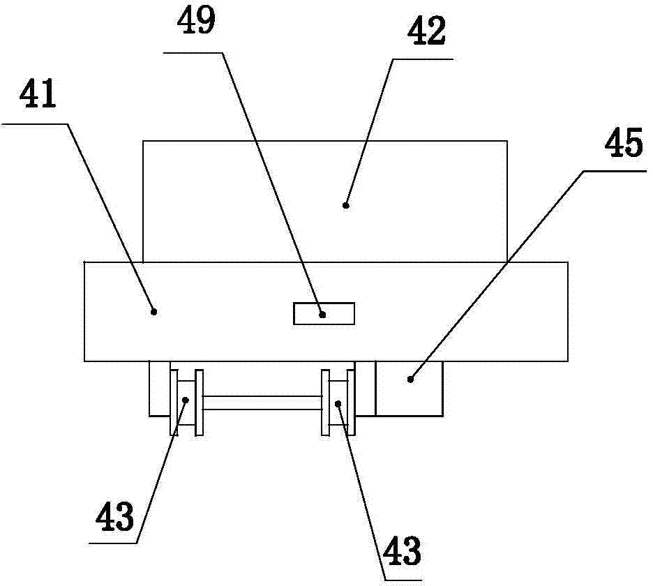
[0028] Such as image 3 As shown, the running assembly 4 comprises a flat plate 41, a retaining ring 42, a track wheel 43, a hook 44, a first motor 45, a fixer 46, a first sp...


PUM


Abstract

The invention discloses a pay-off device and aims to solve the problems that resource waste and hand scratching are easily caused when a user straightens hard wires with hands directly. The pay-off device is characterized in that a front fixed plate and a back fixed plate are fixedly arranged on the ground at an interval, a pair of guide rails is laid between the front fixed plate and the back fixed plate, rail wheels capable of traveling along the guide wheels are arranged at the bottom of a flat plate, a C-shaped retainer ring is arranged at the top of the flat plate, a fixer is arranged in a cavity of the retainer ring, a plurality of arc-shaped movable plates are arranged around the fixer, a first spring is arranged between each movable plate and the fixer, a fixed press plate and a movable press plate which are used for clamping hard wires are arranged on the flat plate, a support is in sliding connection with the guide rails, a projection is formed on one side, close to the flat plate, of the support, a groove is formed in one side of the projection, a movable pin only capable of moving up and down is arranged on the projection, and a hook on the flat plate extends into the groove and then can be penetratingly arranged on the movable pin. The pay-off device is driven by a motor, and accordingly, human hands can be protected from being scratched when used for straightening the hard wires directly.

Description

technical field [0001] The invention relates to the technical field of unwinding wires, in particular to a device for straightening hard wires. Background technique [0002] In electric power construction, especially before wiring in switch cabinets and high-voltage cabinets, it is necessary to straighten the coiled hard wires, then cut them into different lengths, and put on wire numbers. When straightening the hard wire, generally, after breaking the coiled wire reel, tie one end of the hard wire to the angle iron on the bottom surface, and then the person pulls the other end of the hard wire and walks a distance until the wire The disc is completely broken, and then the person pulls the end of the hard wire with bare hands to straighten the hard wire. In this way, hard wires tied to the ground are usually discarded, resulting in a waste of resources. The way of pulling with bare hands will cause strangulation marks on people's hands, and in severe cases, fingers will be...

Claims


Application Information

Patent Timeline
Patent Type & Authority Applications(China)
IPC IPC(8): B65H49/00
Inventor 支应平郭伟杰魏超孙坤
Owner 国网山东济南市历城区供电公司
Why Eureka
Try Eureka