Supercharge Your Innovation With Domain-Expert AI Agents!

Automatic oiling machine of electric construction elevator

A construction elevator, electric technology, applied in elevators, transportation and packaging, etc., can solve the problems of complex structure, inconvenient installation and use, large reduction ratio, etc., and achieve the effect of convenient use and simple structure

Inactive Publication Date: 2015-08-19
张巍
View PDF5 Cites 4 Cited by
  • Summary
  • Abstract
  • Description
  • Claims
  • Application Information

AI Technical Summary

Problems solved by technology

[0005] The purpose of the present invention is to provide an electric construction elevator automatic fuel dispenser with simple structure, convenient installation, reliable use, low price and high quality, which can effectively solve the problem of the complicated structure of the traditional electric or mechanical automatic fuel dispenser for construction elevators. It is inconvenient to install and use, has not been widely used, and the construction industry still maintains the situation of manual regular refueling; effectively solves the problem that the deceleration ratio of the electric or mechanical automatic refueling system for traditional construction elevators is very large, resulting in just installed It takes a long time for the system to run to produce oil; it effectively solves the problem that the traditional electric or mechanical automatic oil dispenser used for construction elevators is also limited to the single direction of the transmission mechanism.

Method used


Image

  • Automatic oiling machine of electric construction elevator
  • Automatic oiling machine of electric construction elevator
  • Automatic oiling machine of electric construction elevator

Examples


Embodiment 1

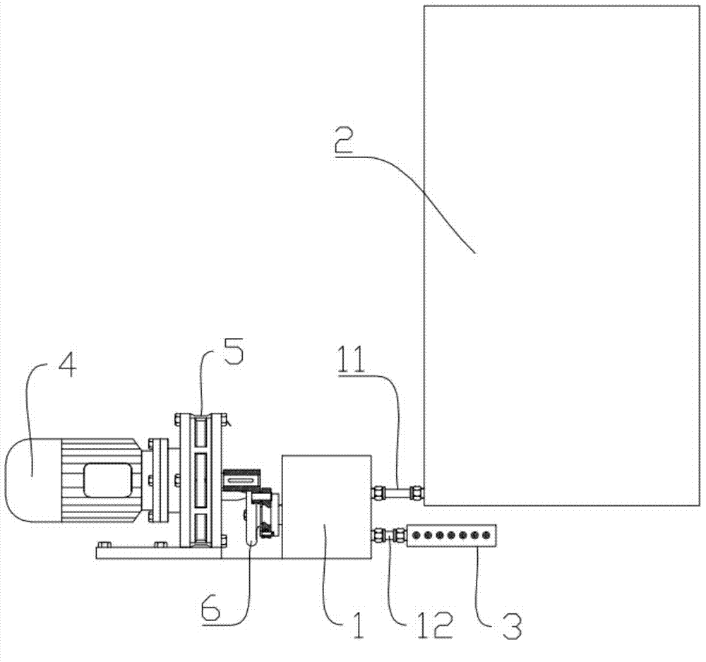
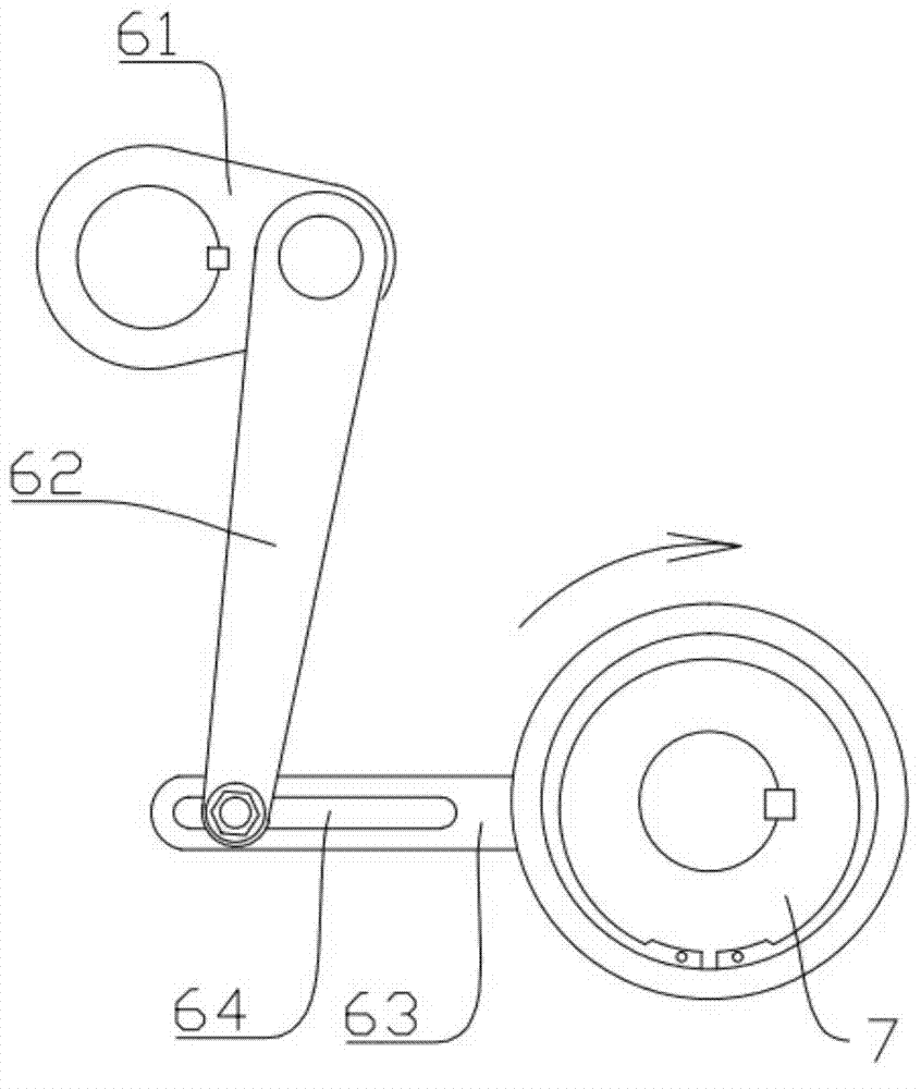
[0033] Embodiment one sees Figure 1 to Figure 3 , comprising an oil pump 1, an oil tank 2, an integrated diverter block 3, a motor 4, and a reducer 5 connected to the output shaft of the motor 4, the oil suction end 11 of the oil pump 1 communicates with the oil tank 2, and the oil pump 1 The oil outlet 12 communicates with the integrated diverter block 3, and the reducer 5 is connected to the oil pump 1 through a transmission assembly. It is characterized in that the oil pumping system formed by the transmission assembly and the oil pump 1 is different in the direction of rotation of the reducer 5 The oil can be pumped out under the condition that the transmission assembly includes a crank-link transmission mechanism 6, the output end of the crank-link transmission mechanism 6 is a one-way bearing 7, the oil pump 1 is a gear pump, and the speed reducer 5 At the same time, it follows the forward and reverse rotation of the motor 4; regardless of the rotation of the front stag...

Embodiment 2

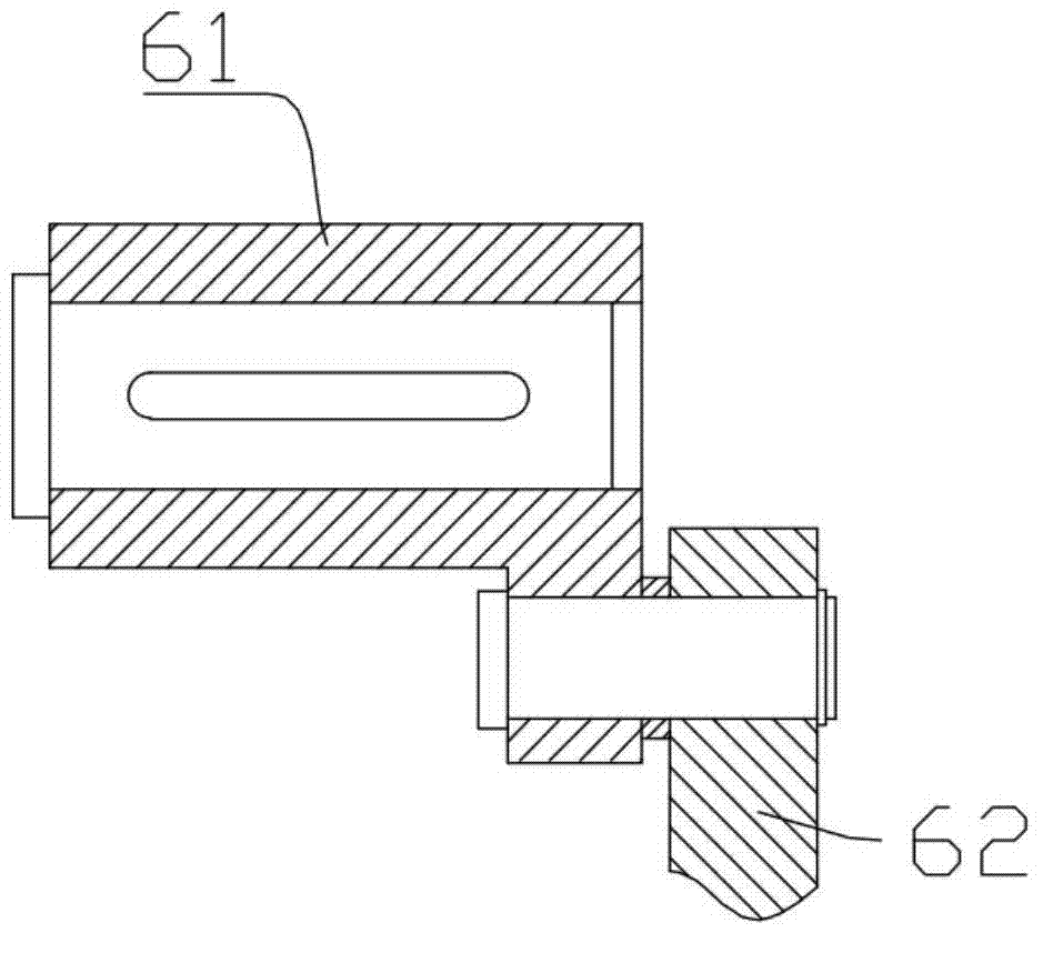
[0038] Embodiment two see Figure 4 to Figure 6 , comprising an oil pump 1, an oil tank 2, an integrated diverter block 3, a motor 4, and a reducer 5 connected to the output shaft of the motor 4, the oil suction end 11 of the oil pump 1 communicates with the oil tank 2, and the oil pump 1 The oil outlet 12 communicates with the integrated diverter block 3, and the reducer 5 is connected to the oil pump 1 through a transmission assembly. It is characterized in that the oil pumping system formed by the transmission assembly and the oil pump 1 is different in the direction of rotation of the reducer 5 The oil can be pumped out under the condition that the transmission assembly includes a crank-link transmission mechanism 6, the output end of the crank-link transmission mechanism 6 is a connecting rod 62, and the oil pump 1 is a plunger pump, and the connecting rod 62 directly pushes the plunger pump, and finally transports it to each lubrication point through the integrated diver...


PUM


Abstract

The invention discloses an automatic oiling machine of an electric construction elevator. The automatic oiling machine comprises an engine oil pump, a engine oil storage tank, an integrated distribution block, a motor and a speed reducer connected with an output shaft of the motor. The engine oil suction end of the engine oil pump is communicated with the engine oil storage tank, the engine oil outlet end of the engine oil pump is communicated with the integrated distribution block, and the speed reducer is in transmission connection with the engine oil pump through a transmission component. The automatic oiling machine is characterized in that the motor and a main elevator lifting motor are connected in parallel.

Description

technical field [0001] The invention relates to an electric construction elevator automatic fuel dispenser. Background technique [0002] With the rapid development of my country's urbanization process, the construction industry has become the leading industry in my country's national economic construction. Construction elevators are the main equipment for vertically transporting building materials in building construction. They must be used in high-rise building construction. During use, the guide rail rollers and racks and pinions must be lubricated. So far, construction elevators produced by most domestic manufacturers are There is no supporting lubricating device, even if some manufacturers install it, the use effect is not ideal, so users can only use high-altitude operations for regular manual filling. Dirty, tiring, dangerous, and inconvenient. [0003] In recent years, some technological innovators have also developed patented new products of electric or mechanical...

Claims


Application Information

Patent Timeline
Patent Type & Authority Applications(China)
IPC IPC(8): B66B7/12
CPCB66B7/1253
Inventor 张巍
Owner 张巍
Features
  • R&D
  • Intellectual Property
  • Life Sciences
  • Materials
  • Tech Scout
  • Unparalleled Data Quality
  • Higher Quality Content
  • 60% Fewer Hallucinations
Learn More