
gear

A technology of gears and teeth, which is applied in the direction of belts/chains/gears, components with teeth, hoisting devices, etc., can solve problems such as fracture of connecting components, achieve improved connection, easy demoulding, and continuous load-bearing capacity Effect

Active Publication Date: 2019-05-10
MIBA SINTER AUSTRIA +1
View PDF12 Cites 0 Cited by
  • Summary
  • Abstract
  • Description
  • Claims
  • Application Information

AI Technical Summary

Problems solved by technology

This can lead to breakage of connecting elements

Method used


Image

  • gear
  • gear
  • gear

Examples


Embodiment Construction

[0026] At the outset, it should be pointed out that the same reference numerals or the same component designations are used for the same components in different embodiments, wherein the disclosure content contained in the entire description can be referred to the components with the same reference numerals or the same component designations. Likewise, selected positions in the description such as above, below, side, etc. relate to the direct description and to the illustrated figures and, if the position is changed, are automatically transferred to the new position.

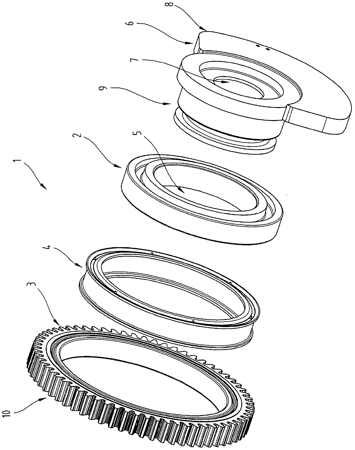
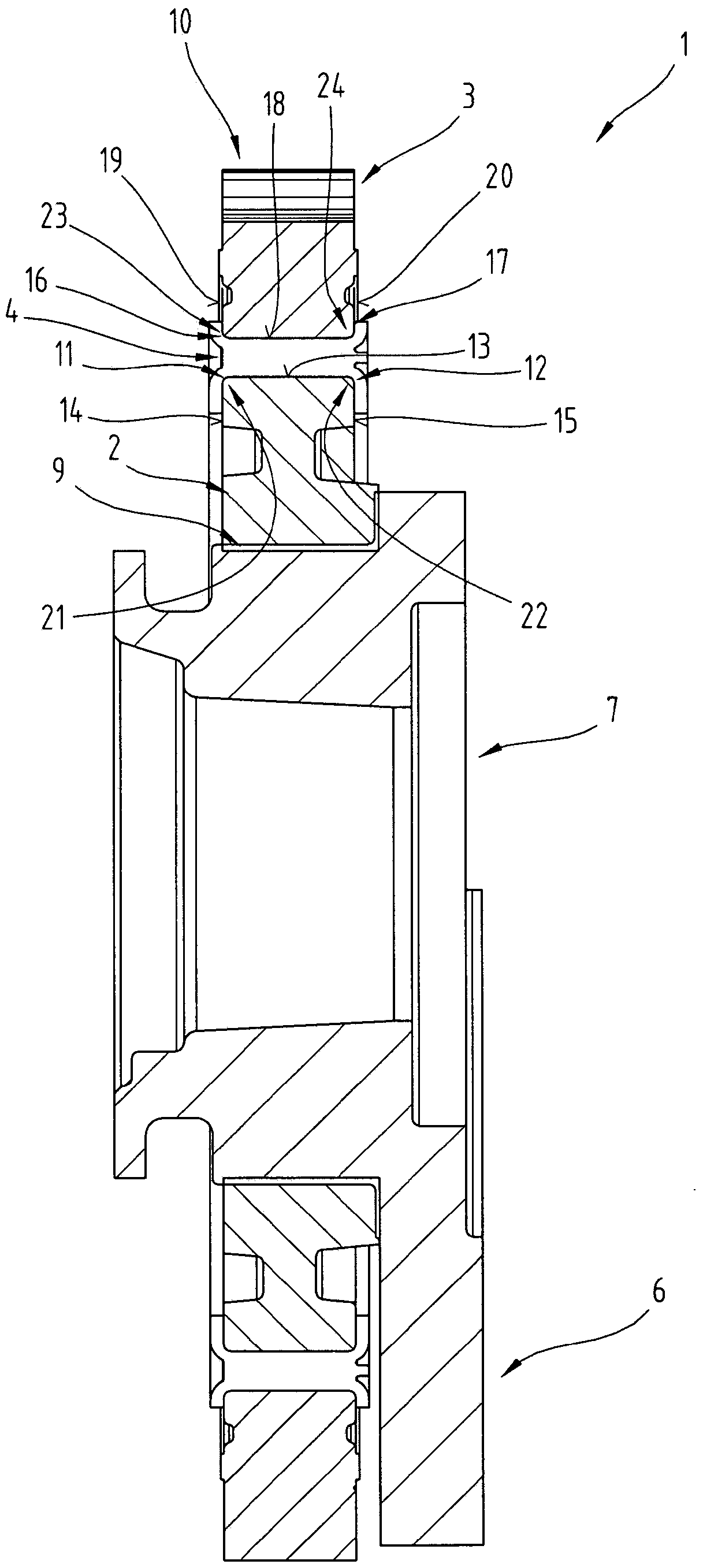
[0027] exist figure 1 with 2 A first embodiment of the gear 1 is shown in . The gear 1 comprises a first radially inner ring element 2 , a second radially outer ring element 3 and a connecting element 4 . The first radially inner ring element 2 can also be referred to as a hub part and the second radially outer ring element 3 can also be referred to as a toothed ring.

[0028] The first radially inner ring ele...


PUM


Abstract

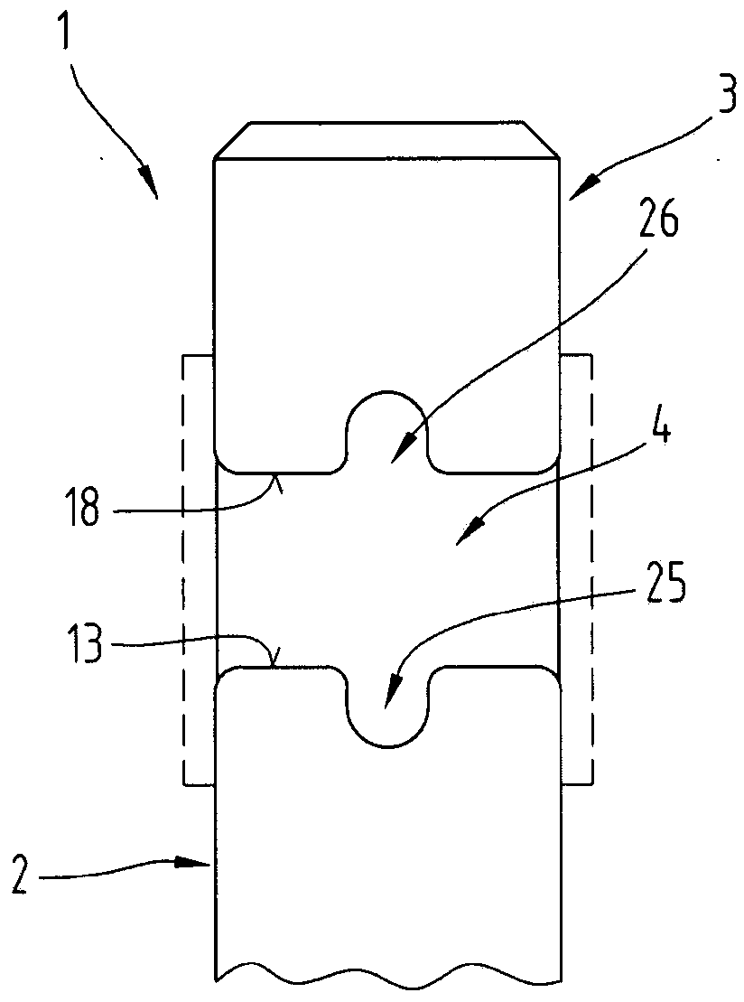
The invention relates to a gear (1) comprising a first radially inner annular element (2), a second radially outer annular element (3) and a connecting element (4), the second radially outer annular The element (3) has a toothing (10), and the connecting element is arranged in the radial direction between a first radially inner annular element (2) and a second radially outer annular element (3) and is connected to the first radially The inner ring element is connected to the second radially outer ring element, the connecting element (4) being at least partially made of a rubber-elastic material. Here, the edges (11, 12) of the first radially inner ring element (2) in the connecting region between the first radially inner ring element (2) and the connecting element and the second radially outer ring element The edges (16, 17) of the element (3) in the connection region between the second radially outer annular element (3) and the connection element (4) are provided with roundings (21 to 24).

Description

technical field [0001] The invention relates to a gear comprising a radially inner ring element, a radially outer ring element and a connecting element, the radially outer ring element has a tooth portion, and the connecting element is arranged in the radial direction on the radially inner The ring element is connected to the radially outer ring element and the radially inner ring element and the radially outer ring element, and the connection element is at least partially made of rubber elastic material. Background technique [0002] Balance shafts are known for reducing vibrations caused by free inertial forces and moments of inertia in internal combustion engines. The balance shaft is usually driven by a crankshaft, for which purpose the crankshaft is operatively connected to the balance shaft via a gear. In order to reduce the noise of the toothing between the balancer shaft and the crankshaft and to absorb vibrations, split gears are known from the prior art, the two p...

Claims


Application Information

Patent Timeline
Patent Type & Authority Patents(China)
IPC IPC(8): F16H55/17
CPCF16H55/14F16H55/17F16H2057/126Y10T74/19898F16H55/18
Inventor C·杜曼斯基S·魏安德J·德普
Owner MIBA SINTER AUSTRIA
Learn More