Drive motor for electric vehicle

Inactive Publication Date: 2012-12-20
NTN CORP
View PDF0 Cites 0 Cited by
  • Summary
  • Abstract
  • Description
  • Claims
  • Application Information

AI Technical Summary

Benefits of technology

[0012]In the present invention, the first and second non-round shaped portions of the rotor core portion and the rotary output shaft may be in the form of flat surfaces, which are parallel to an axial direction and perpendicular to a radial direction and which are adapted to be mated with each other. The use of the flat surfaces is effective to avoid a notch effect and also to make it further hard for the strength to lower which would otherwise occur when the non-round shaped portions are employed.
[0013]In the present invention, the first and second non-round shaped portions of the rotor core and the rotary output shaft may be of recessed and projected shapes, respectively, the recessed and projected shapes extending in the axial direction. By way of example, the first non-round shaped portion of the rotor core portion may be in the form of a projection protruding towards an inner diametric side, in which case the second non-round shaped portion of the rotary output shaft is in the form of a recess depressed towards the inner diametric side and is engageable with the projection. Alternatively, the non-round shaped portion of the rotor core portion may be in the form of a recess depressed towards an outer diametric side, in which case the second non-round shaped portion of the rotary output shaft is in the form of a projection protruding towards the outer diametric side and is engageable with the recess. If the non-round shaped portions represent respective recessing and projecting shapes extending in the axial direction, a work can be facilitated to make the non-rounded shaped portions to be engaged with each other by means of a mounting work of the rotor core portion and the rotary output shaft and, also, a firm detention or arresting effect can be obtained.
[0014]The first non-rounded shaped portion of the rotor core portion may be in the form of a first recess depressed towards an outer diametric side and the second non-round shaped portion of the rotary output shaft is preferably in the form of a second recess depressed towards an inner diametric side, a

Problems solved by technology

However, setting the radial wall thickness of the rotor core member in itself to a large value is undesirable from the as

Method used


Image

  • Drive motor for electric vehicle
  • Drive motor for electric vehicle
  • Drive motor for electric vehicle

Examples


Embodiment Construction

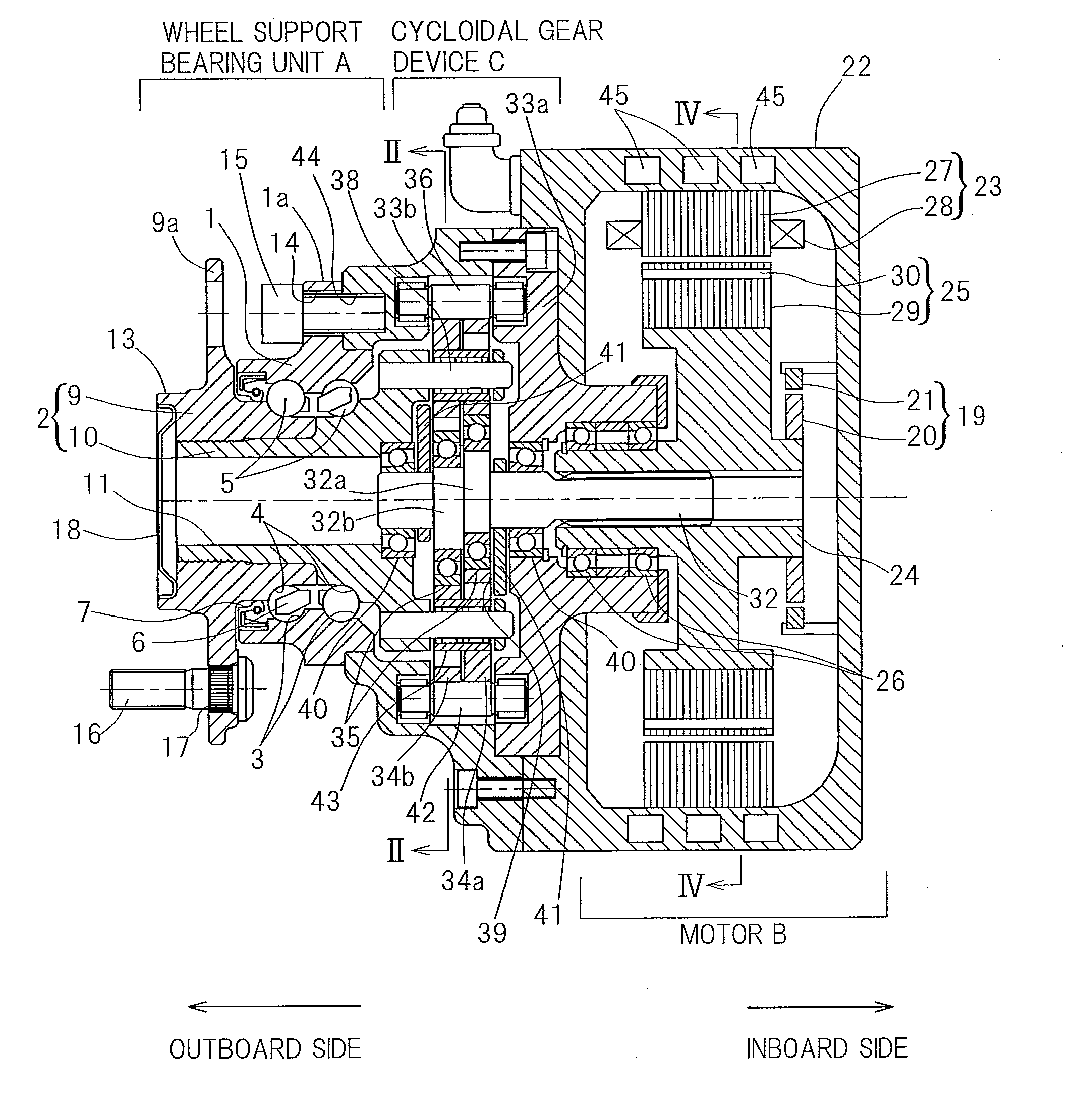
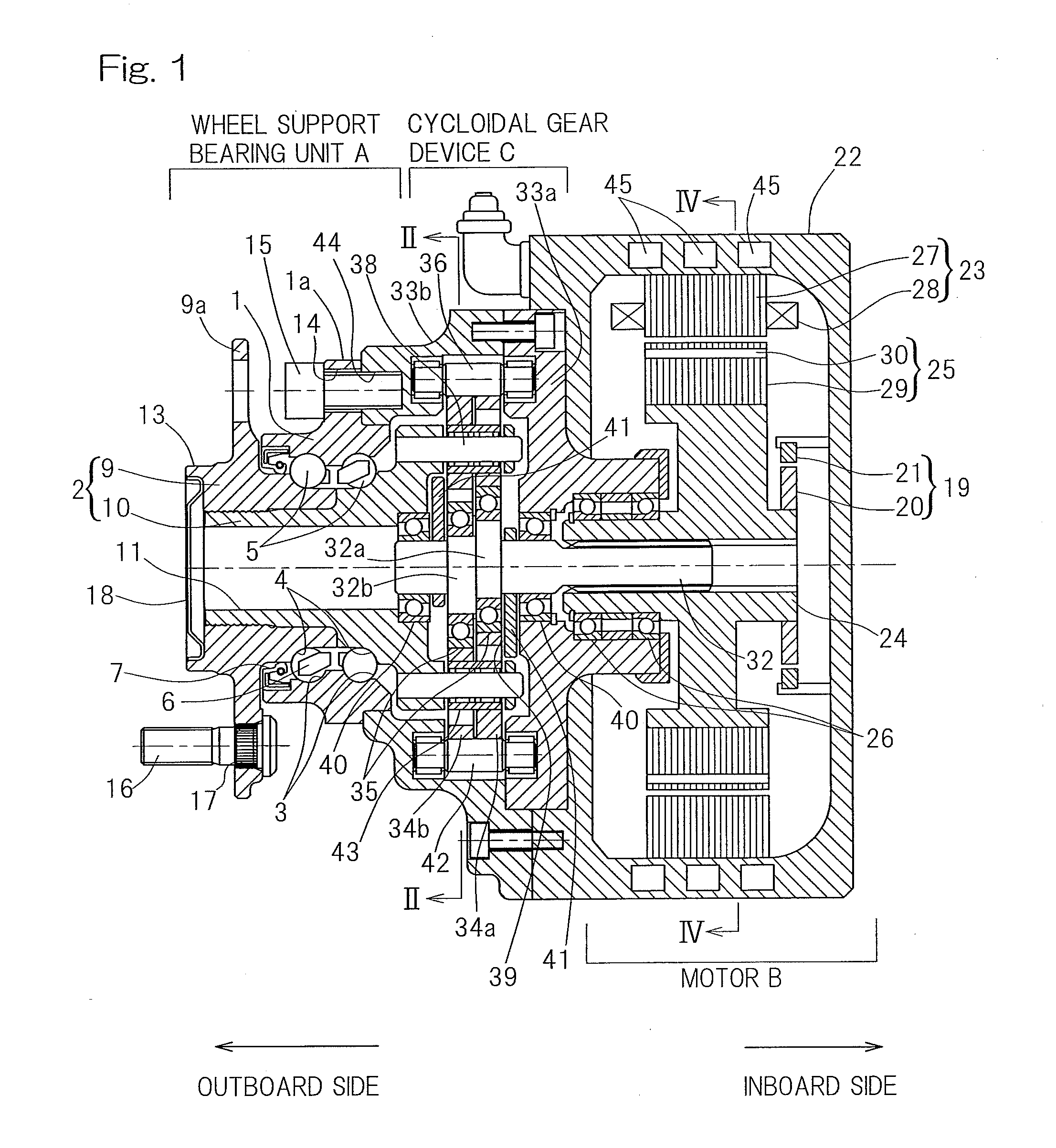
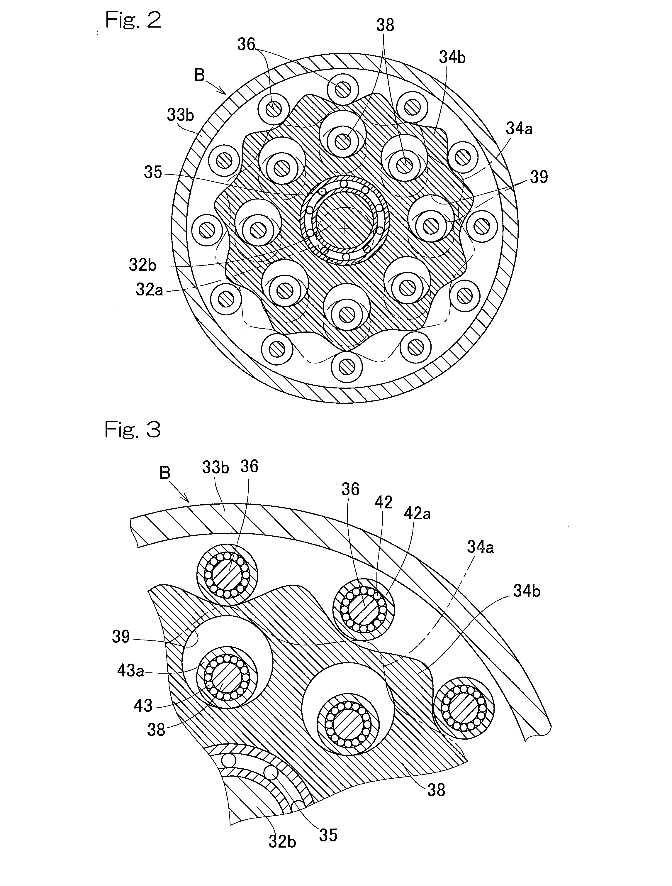
[0026]FIGS. 1 to 4 illustrates a first preferred embodiment of the present invention. In particular, FIG. 1 illustrates a longitudinal sectional view of a wheel support bearing assembly incorporating therein a drive motor for an electric vehicle designed in accordance with the first preferred embodiment of the present invention. The wheel support bearing assembly shown therein is a wheel support bearing assembly of an in-wheel motor incorporated type, in which a reduction gear unit C is interposed between a wheel support bearing unit A for the automotive vehicle and the drive motor B according to the first embodiment of the present invention and a hub for a vehicle drive wheel, supported by the wheel support bearing unit A, and a rotary output shaft 24 of the drive motor B are coaxially connected with each other. The reduction gear unit C is a cycloidal gear device of a structure, in which a rotary input shaft 32 drivingly coupled coaxially with the rotary output shaft 24 of the dri...


PUM


Abstract

A drive motor for an electric vehicle is an IPM motor including a motor rotor (25), which is made up of a rotor core portion (29) having an inner peripheral surface, which is mounted externally on a rotary output shaft (24) and which is round in sectional shape, and a permanent magnet (30) disposed within the rotor core portion (29). At a circumferential position which will become proximate to a site of the permanent magnet (30), displaced towards an outer diametric side of the rotor core portion (29), an inner peripheral surface of the rotor core portion (29) and an outer peripheral surface of the rotary output shaft are provided with respective non-round shaped portions (29a, 24a) of a circular shape in section, which form respective parts of a detention or arresting unit (31) for arresting the motor rotor (25) from rotating relative to the rotary output shaft (24).

Description

CROSS REFERENCE TO THE RELATED APPLICATION[0001]This application is a continuation application, under 35 U.S.C. §111(a), of international application No. PCT / JP2011 / 054588, filed Mar. 1, 2011, which claims priority to Japanese patent application No. 2010-047791, filed Mar. 4, 2010, the entire disclosure of which is herein incorporated by reference as a part of this application.BACKGROUND OF THE INVENTION[0002]1. Field of the Invention[0003]The present invention relates to a drive motor for an electrically powered automotive vehicle, which may be used as an electric in-wheel motor built in a wheel of the automotive vehicle.[0004]2. Description of Related Art[0005]If a vehicle drive motor and / or a controller for controlling the vehicle drive motor, both employed in the electrically powered automotive vehicle, or electric vehicle for short, fail to operate, the outcome would be a fatal situation that takes place, and, accordingly, those failures should be absolutely avoided in terms of...

Claims


Application Information

Patent Timeline
IPC IPC(8): H02K7/14
CPCY02T10/641H02K1/30H02K1/28Y02T10/64
Inventor OZAKI, TAKAYOSHIMAKINO, YUSUKEOKADA, KOICHI
Owner NTN CORP
Why Eureka
Try Eureka