Piston pump, particularly high-pressure fuel pump for internal combustion engine

A technology of piston pump and internal combustion engine, which is applied in the direction of fuel injection pump, fuel injection device, pump, etc., can solve problems such as high cost, and achieve the effects of reducing component cost, small structure size, and simple manufacturing.

Active Publication Date: 2020-03-31
ROBERT BOSCH GMBH
View PDF6 Cites 0 Cited by
  • Summary
  • Abstract
  • Description
  • Claims
  • Application Information

AI Technical Summary

Problems solved by technology

Such gap seals require high precision in the manufacture and ass

Method used


Image

  • Piston pump, particularly high-pressure fuel pump for internal combustion engine
  • Piston pump, particularly high-pressure fuel pump for internal combustion engine
  • Piston pump, particularly high-pressure fuel pump for internal combustion engine

Examples


Embodiment Construction

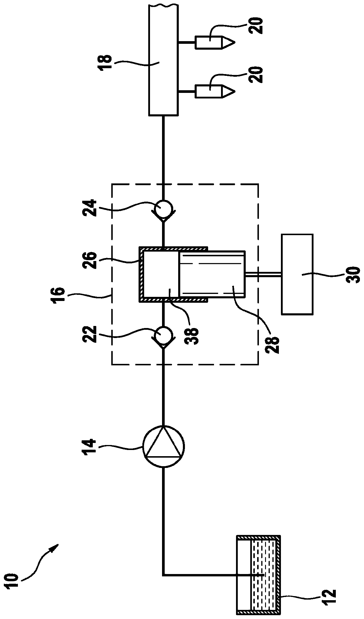
[0036] The fuel system of an internal combustion engine is figure 1 The middle bears the reference number 10 as a whole. The fuel system comprises a fuel container 12 from which an electric pre-delivery pump 14 delivers fuel to a high-pressure fuel pump designed as a piston pump 16 . The high-pressure fuel pump delivers fuel further to a high-pressure fuel rail 18 , to which a plurality of fuel injectors 20 are connected, which inject fuel into the combustion chambers of the internal combustion engine, not shown.

[0037] The piston pump 16 includes an inlet valve 22 , an outlet valve 24 and a pump housing 26 . A pump piston 28 is received in the pump housing so as to be movable back and forth. The pump piston 28 is set in motion by a drive 30, wherein the drive 30 figure 1 is shown schematically only. The drive 30 can be, for example, a camshaft or an eccentric shaft. The inlet valve 22 is designed as a flow control valve by means of which the fuel quantity delivered by ...


PUM


Abstract

The invention relates to a piston pump (16), in particular high-pressure fuel pumps for an internal combustion engine, comprising a pump housing (26), a pump piston (28) and a conveying chamber (38) defined at least by the pump housing (26) and the pump piston (28). According to the invention, a seal (44) for sealing the conveying chamber (38) and a separate guide element (46) for guiding the pumppiston (28) are arranged preferably between the pump housing (26) and the pump piston (28). The seal (44) is designed as a metal sleeve and rests on the pump housing (26).

Description

technical field [0001] The invention relates to a piston pump according to the preamble of claim 1 , in particular a high-pressure fuel pump for an internal combustion engine. Background technique [0002] Piston pumps are known from the prior art, which are used, for example, in internal combustion engines with gasoline direct injection. This piston pump has a gap seal between the pump cylinder and the pump piston. The pump cylinder and pump piston are typically fabricated from stainless steel. Such gap seals require high precision during the manufacture and assembly of the pump cylinder and the pump piston, resulting in high costs. The ever-present gap, the size of which cannot be reduced arbitrarily, for example due to the thermal expansion coefficients of the materials used, leads to a suboptimal volumetric efficiency, especially at low rotational speeds. Contents of the invention [0003] The object of the invention is to realize a piston pump which has sufficient ...

Claims


Application Information

Patent Timeline
IPC IPC(8): F04B1/0448F04B1/0439F04B1/0408F02M59/44F02M59/02
CPCF04B1/0408F04B1/0421F04B1/0439F04B1/0448F02M59/442
Inventor S·芙洛K·科赫F·尼切A·普利施D·乌伦布洛克J·吉斯勒E·卡基尔
Owner ROBERT BOSCH GMBH
Why Eureka
Try Eureka