Reflective LC devices including thin film metal grating

A liquid crystal device and metal grating technology, applied in the field of variable phase retarders, can solve the problems of reducing device yield, complicating LCoS processing technology, reducing polarization sensitivity of reflective liquid crystal devices, etc., and achieving the effect of reducing polarization sensitivity

Active Publication Date: 2015-08-19
LUMENTUM OPERATIONS LLC
View PDF8 Cites 11 Cited by
  • Summary
  • Abstract
  • Description
  • Claims
  • Application Information

AI Technical Summary

Problems solved by technology

Although they require less relief depth than FB gratings based on alternating dielectrics, implementing them on the surface of the LCOS pixel electrode greatly complicates the LCoS process and reduces device yield.
[0006] Accordingly, it will be appreciated that there may be significant problems and disadvantages with existing solutions and techniques involving reducing the polarization sensitivity of reflective liquid crystal devices and with regard to optical wave plates that may be included in such devices

Method used


Image

  • Reflective LC devices including thin film metal grating
  • Reflective LC devices including thin film metal grating
  • Reflective LC devices including thin film metal grating

Examples


Embodiment Construction

[0028] In the following description, for purposes of explanation and not limitation, specific details are set forth, such as particular optical and electrical components, components, techniques, materials, etc., in order to provide a thorough understanding of the present invention. It will be apparent, however, to one skilled in the art that the present invention may be practiced in other embodiments that depart from these specific details. In other instances, detailed descriptions of well-known methods, devices, components, and circuits have been omitted so as not to obscure the description. It should be noted that the terms "first", "second", etc. used herein do not imply an ordering, but are only used to distinguish one element from other elements, except where expressly stated. The terms "transparent" or "opaque" etc. refer to being substantially transparent to light having a wavelength of the target operating wavelength. The term "subwavelength" when used in conjunction w...


PUM

PropertyMeasurementUnit
Pitchaaaaaaaaaa
Widthaaaaaaaaaa
Thicknessaaaaaaaaaa

Abstract

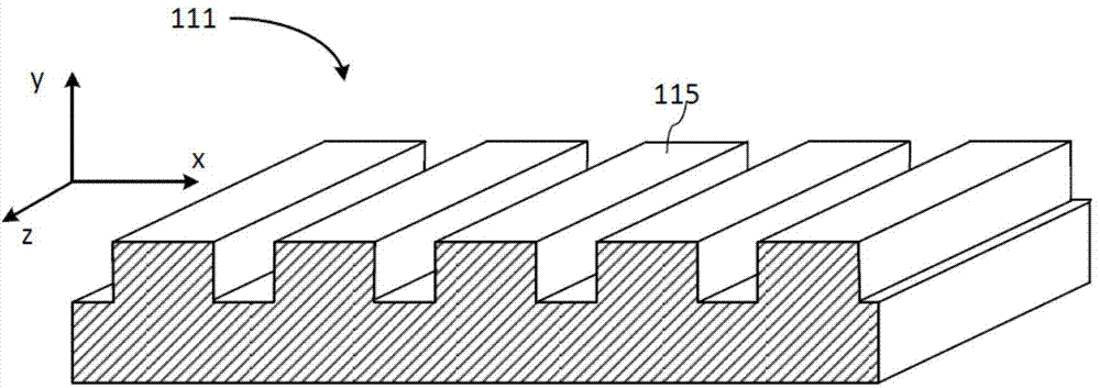
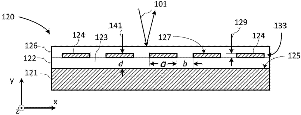
A sub-wavelength thin-film metal grating is placed inside a liquid crystal variable optical retarder at a selected distance from a reflective electrode to form a reflective half wave plate, thereby reducing polarization dependence of the optical retardation generated by the variable optical retarder. The approach enables to form within the device the reflective half wave plate that is suitably thin without modifying the reflective electrode of the device.

Description

technical field [0001] The present invention relates to liquid crystal devices and, in particular, to reflective liquid crystal based light modulators and phase variable retarders employing formal birefringent wave plates, and methods for their manufacture. Background technique [0002] Optical devices using liquid crystals are well known in the art and have been used in a variety of applications, including optical phase modulators and phase variable retarders for forming variable optical phase retardation and / or changing the polarization state of a light beam. Reflective liquid crystal devices can be conveniently fabricated using the well-established liquid crystal on silicon (LCoS) technology. In a typical liquid crystal on silicon, a liquid crystal layer a few micrometers (μm) thick is sandwiched between a transparent electrode and a reflective electrode formed on a silicon substrate that also houses the circuitry needed to drive the device . When a voltage is applied a...

Claims


Application Information

Patent Timeline
IPC IPC(8): G02F1/1335G02F1/1343G02F1/1333
CPCG02F2001/133638G02F1/134309G02F1/1339G02F1/133553G02F1/13363G02F1/1333G02F1/133504G02F1/1343G02F2201/307G02F1/133567G02F1/133638G02B5/3058G02F1/13439G02F2201/305G02F2203/50
Inventor 基思·安德森约翰·迈克尔·米勒海利·戴杰田鲁
Owner LUMENTUM OPERATIONS LLC
Why Eureka
Try Eureka