
Device and method for measuring parallelism of ion beam flow

An ion beam, parallelism technology, applied in the direction of discharge tubes, electrical components, circuits, etc., can solve the problems of inconvenience, high cost, inaccurate judgment results, etc., and achieve the effect of cost saving

Inactive Publication Date: 2015-08-19
EVERDISPLAY OPTRONICS (SHANGHAI) CO LTD
View PDF5 Cites 1 Cited by
  • Summary
  • Abstract
  • Description
  • Claims
  • Application Information

AI Technical Summary

Problems solved by technology

[0007] The purpose of the present invention is to overcome the inaccurate, high cost and inconvenient defects of the method for measuring whether the ion beam currents are parallel in the prior art, and provide an accurate, simple and cheap device and method for measuring the parallelism of the ion beam currents. method

Method used


Image

  • Device and method for measuring parallelism of ion beam flow
  • Device and method for measuring parallelism of ion beam flow
  • Device and method for measuring parallelism of ion beam flow

Examples


Embodiment 1

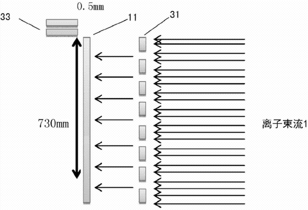
[0072] Such as image 3 As shown, the ion beam 1 to be measured (ion beam implanter model Magic-I70, manufacturer MES-Afty company, ion source BF3, voltage 80KeV) is irradiated on the substrate through the ion beam penetration unit 31 The glass substrate 11 is placed on the unit, and the current on the glass substrate 11 is measured by the current collection unit (included in the ion beam implanter) 33, and the glass substrate 11 placed on the substrate placement unit is connected with the ion beam The flow through the unit 31 is parallel.

[0073] The ion beam passing unit 31 is a graphite jig, the width of the slits is 8 mm, and the distance between the slits is 100 mm.

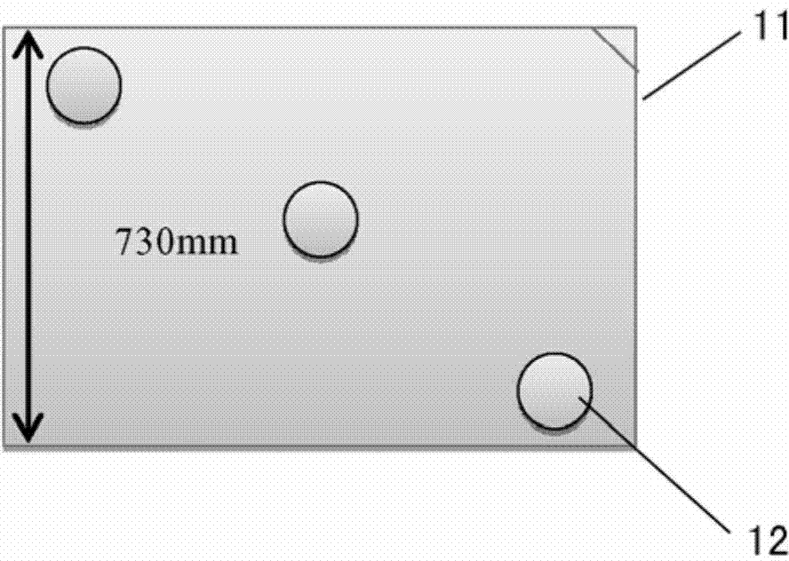
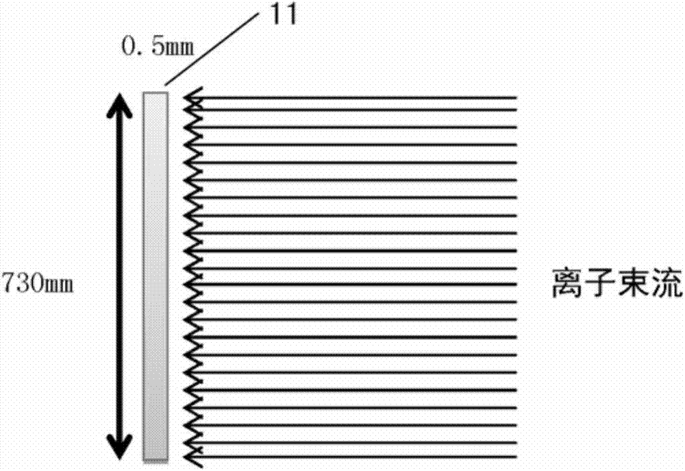
[0074] The size of the glass substrate 11 is 730mm*920mm.

[0075] Moreover, the distance between the ion beam current passing unit 31 and the glass substrate 11 is 1.5 meters.

[0076] The measured results are as Figure 4 shown in Figure 4 Among them, the horizontal axis represents the ion beam curr...

Embodiment 2

[0079] Such as Figure 5 As shown, the ion beam current 2 to be measured (ion beam implanter model Magic-I70, manufacturer MES-Afty company, ion source BF3, voltage 80KeV) passes through the ion beam current penetration unit 31, and shoots at The glass substrate 11 placed on the substrate placement unit, and the current on the glass substrate 11 is measured by the current collection unit (included in the ion beam implanter) 33, and the glass substrate 11 placed on the substrate placement unit is connected to the The ion beam flows through the unit 31 in parallel.

[0080] The ion beam passing unit 31 is a graphite jig, the width of the slits is 8 mm, and the distance between the slits is 200 mm.

[0081] And, the size of the glass substrate 11 is 730mm*920mm

[0082] In addition, the ion beam flows through the unit 31 , and the distance between the ion beam and the glass substrate 11 is 1.5 meters.

[0083] The measured results are as Figure 6 shown in Figure 6 , the ho...


PUM


Abstract

The invention provides a device and a method for measuring parallelism of an ion beam flow. The device comprises the components of a substrate placing unit for placing the substrate whereon; an ion beam flow penetration unit which is provided with a plurality of splits that allow penetration of the ion beam flow and is parallel with the substrate that is placed on the substrate placing unit; a current collecting unit which measures the current on the substrate; and a position comparison unit which is used for comparing with a current position on the measured substrate. Through the device or the method for measuring parallelism of the ion beam flow, the parallelism of the ion beam flow can be obtained directly and simply, thereby preventing effects of a channel effect of the ions in a silicon wafer, ion activation equipment temperature homogeneity and resistance measuring equipment accuracy in determining the resistance uniformity according to a traditional method. Furthermore the ion beam penetration unit can be used repeatedly, and a cost for purchasing silicon wafers can be saved.

Description

technical field [0001] The invention relates to a device and method for measuring the parallelism of ion beam current. Background technique [0002] As the manufacturing process of semiconductor integrated circuits becomes more and more miniaturized, the performance requirements for semiconductor manufacturing equipment are also getting higher and higher. Ion beam implanter is a very important doping equipment in the manufacture of semiconductor devices. In order to ensure the consistency of device performance on the entire wafer, it is necessary to confirm the parallelism of the ion beam before ion implantation to ensure that the beam is implanted vertically into the polysilicon layer, otherwise it will affect the concentration distribution of ions in the polysilicon, and then affect the polysilicon In-plane resistance value uniformity and TFT current uniformity. [0003] In the production process of ion beam implantation, the ion beam implanter is fixed, and the substrat...

Claims


Application Information

Patent Timeline
Patent Type & Authority Applications(China)
IPC IPC(8): H01J37/244
CPCH01J37/244
Inventor 严晓龙吴建宏彭思君钟尚骅
Owner EVERDISPLAY OPTRONICS (SHANGHAI) CO LTD
Features
  • Generate Ideas
  • Intellectual Property
  • Life Sciences
  • Materials
  • Tech Scout
  • Unparalleled Data Quality
  • Higher Quality Content
  • 60% Fewer Hallucinations
Learn More