LED lighting device for an operating field comprising a light beam divider

A lighting device and beam splitter technology, which is applied to lighting devices, fixed lighting devices, components of lighting devices, etc., can solve the problems of color shadows, uneven light intensity, and it is difficult for lighting devices to obtain uniform lighting.

Inactive Publication Date: 2015-08-19
MAQUET SAS
View PDF9 Cites 0 Cited by
  • Summary
  • Abstract
  • Description
  • Claims
  • Application Information

AI Technical Summary

Problems solved by technology

Unfortunately, the beams from the two types of LEDs are differentiated and the resulting amount of light is not uniform
Furthermore, this lighting device has the disadvantage that when the user looks at the lighting device, it can be seen the color temperature of alternating warm white and cool white light corresponding to the two types of LEDs used, which causes visual discomfort
However, such a light guide has the disadvantage of reducing the optical yield of the lighting device due to the technical difficulty of injecting the luminous flux emitted by the light source into the light guide.
Therefore, the electric power consumption of such a lighting device is high
In addition, it is difficult to obtain uniform illumination with this type of lighting device, and the illumination of the surgical field varies according to the color temperature selected by the user
In addition, this type of lighting device has other disadvantages, such as the disadvantage of producing colored shadows in lighting situations when obstacles obscure a part of the luminous flux

Method used


Image

  • LED lighting device for an operating field comprising a light beam divider
  • LED lighting device for an operating field comprising a light beam divider
  • LED lighting device for an operating field comprising a light beam divider

Examples


Embodiment Construction

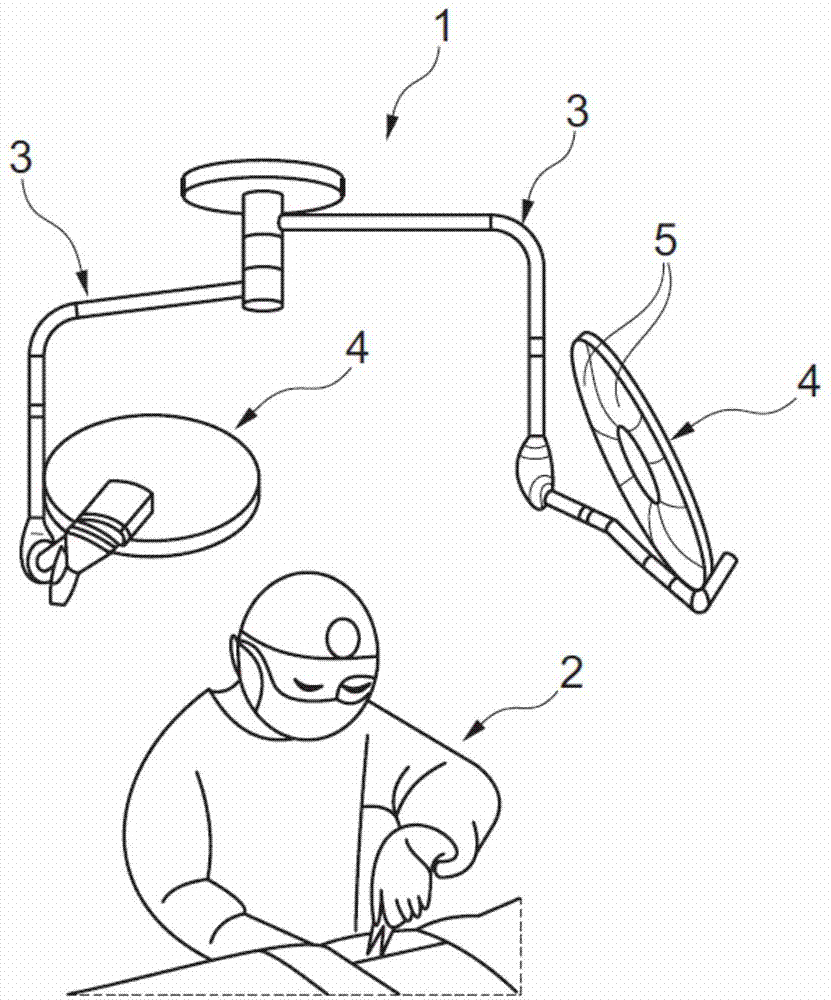
[0037] figure 1 Illumination system 1 is shown for illuminating an illuminated surgical site 2 , which in the present example is a surgical site in which a surgeon operates on a patient. In this example, the lighting system 1 is of the type suspended from the ceiling of an operating room in a manner known per se and, in this example, has two articulated suspension arms 3 each Invented lighting dome 4 of multiple lighting devices 5 .

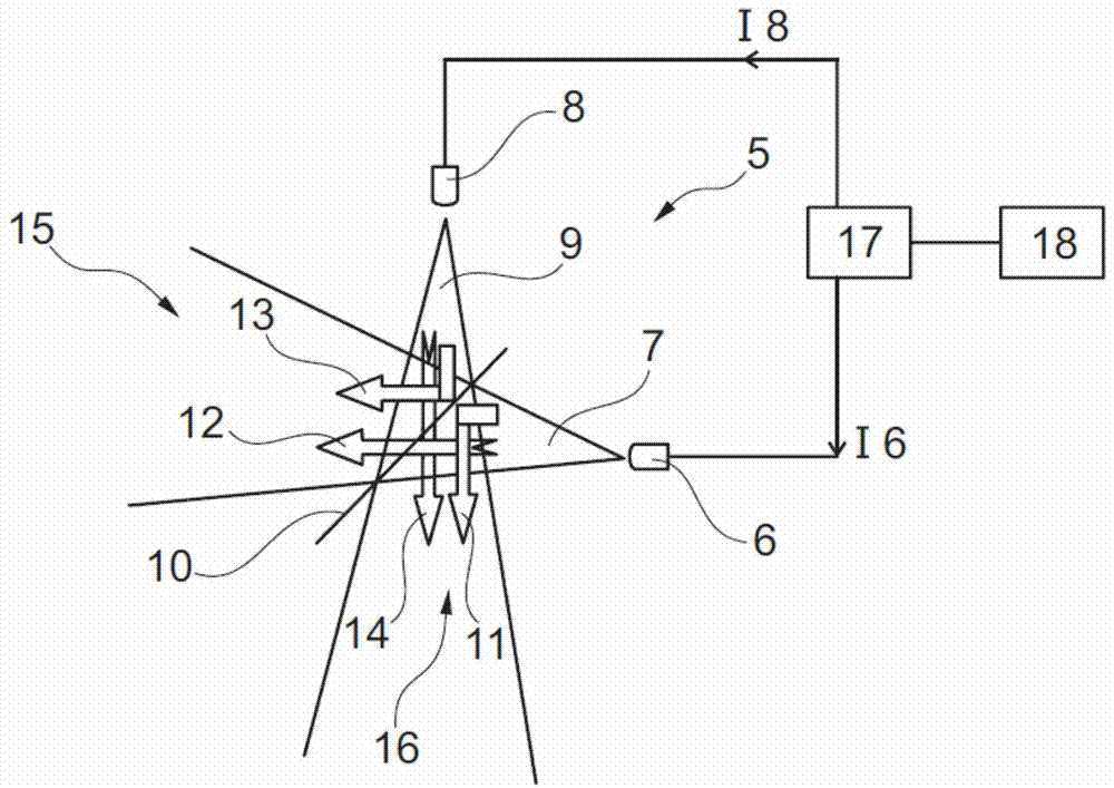
[0038] figure 2 is a diagram showing the principle of the lighting device 5 of the present invention, which in this example includes: a first LED 6 arranged to emit a first white light beam 7 having a first color temperature Tk1; and a second LED 8, which is arranged to emit a second white light beam 9 having a second color temperature Tk2 different from said first color temperature.

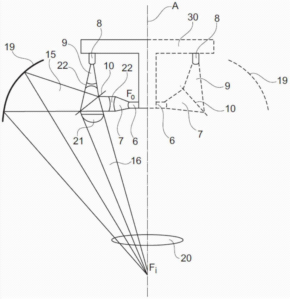
[0039] The lighting device 5 further comprises a beam splitter 10 arranged to split the first white light beam 7 into a first first beam portion 11 reflected b...


PUM


Abstract

An LED lighting device (5) comprises first and second LEDs (6, 8) arranged to respectively emit first and second beams (7, 9) of white light having first and second different respective colour temperatures, and a beam splitter (10) arranged to split the first and second light beams (7, 9) respectively into a first reflected portion of the first and second beams (11, 3) and a second transmitted portion of the first and second beams (12, 14). The LED's (6, 8) and the beam splitter (10) are arranged spatially such that the transmitted portion of the first beam (12) and the reflected portion of the second beam (13) overlap into a first resulting beam (15) of intermediate colour temperature between the first and second colour temperatures, and the reflected portion of the first beam (11) and the transmitted portion of the second beam (14) overlap into a second resulting beam (16) of the same intermediate colour temperature.

Description

technical field [0001] The present invention relates to lighting devices with light emitting diodes (LEDs), especially medical lighting fixtures for illuminating surgical settings. Background technique [0002] In a medical environment, especially in an operating room, the lighting conditions should be suitable to enable a user (eg, a surgeon or a physician) to work properly. In particular, the lighting should be as uniform as possible, so that the user can distinguish between various types of tissue located within the lighting scene. [0003] Furthermore, the lighting, which is white lighting as a whole, should meet certain standards and should produce light with a color rendering index (CRI) ranging from 85 to 100 and a color temperature ranging from 3000 Kelvin (K) to 6700K . The term "color temperature" of light is understood here to mean the equivalent color temperature evaluated in a conventional manner in the chromaticity diagram of the International Commission on I...

Claims


Application Information

Patent Timeline
Patent Type & Authority Applications(China)
IPC IPC(8): F21K99/00F21W131/205F21Y101/02F21Y113/00
CPCG02B19/0066F21W2131/205G02B27/1006G02B27/144F21Y2101/02G02B19/0023F21Y2113/005F21Y2115/10F21Y2107/00F21Y2113/13F21Y2101/00F21Y2113/10F21V23/003F21V5/04F21S8/043F21V7/08F21V13/04F21V23/02G02B27/1073
Inventor 塞西莉亚·瓦尔特奥明-宏·乌·特惠
Owner MAQUET SAS
Why Eureka
Try Eureka