Method for predicting the usability of a relay or a contactor

A technology of relays and protectors, applied in the field of forecasting the availability of relays or protectors

Active Publication Date: 2015-08-19
ROBERT BOSCH GMBH +1
View PDF7 Cites 5 Cited by
  • Summary
  • Abstract
  • Description
  • Claims
  • Application Information

AI Technical Summary

Problems solved by technology

The disadvantage of such a device is that additional components must necessarily be provided on the relays to be monitored

Method used


Image

  • Method for predicting the usability of a relay or a contactor
  • Method for predicting the usability of a relay or a contactor

Examples


Embodiment Construction

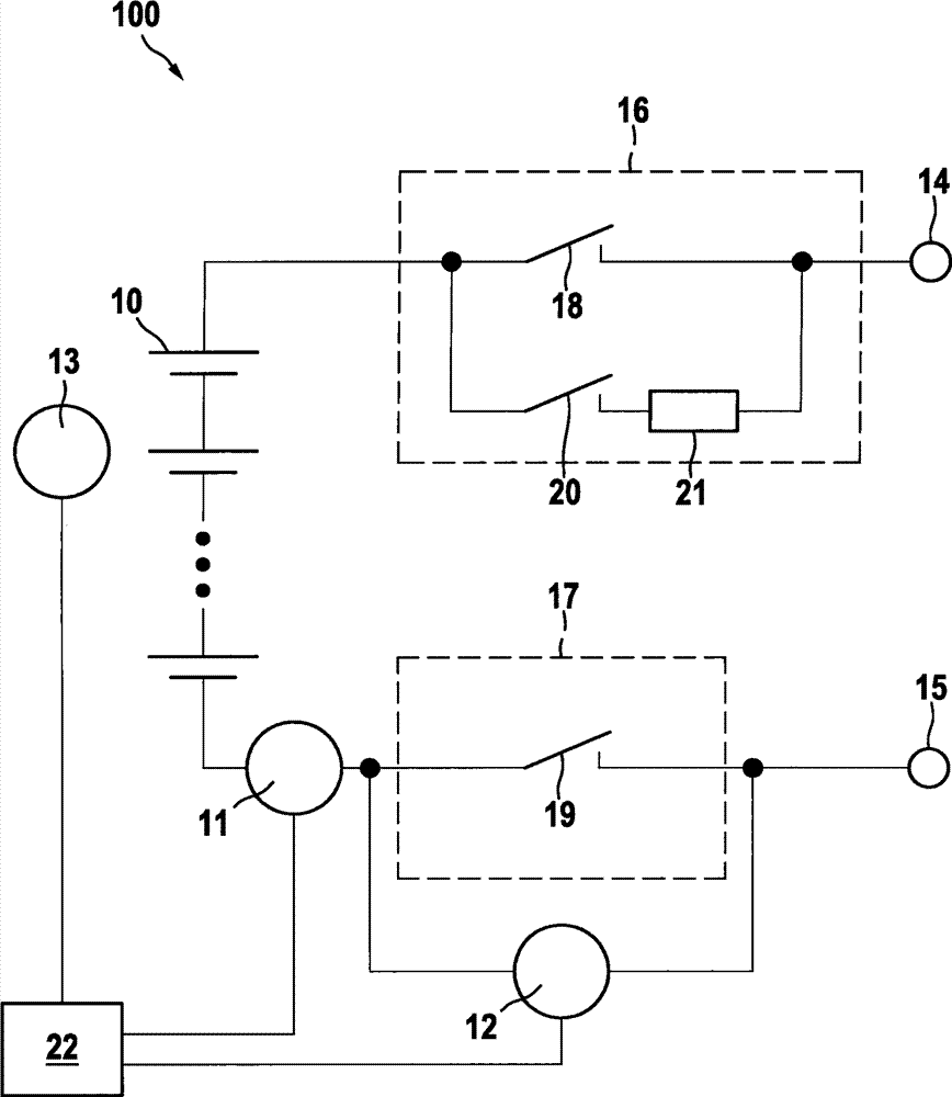
[0018] figure 1 An accumulator generally designated 100 is shown in a block diagram. A plurality of battery cells 10 are connected in series and optionally additionally in parallel in order to achieve the high output voltage and battery capacity desired for the respective application. A charging and disconnecting device 16 is connected between the positive pole of the battery cell and the positive battery terminal 14 . In addition, a disconnecting device 17 is connected between the negative pole of the battery cell 10 and the negative battery terminal 15 . The disconnecting and charging device 16 and the disconnecting device 17 each comprise a protector 18 or 19 which is provided for disconnecting the battery cells from the battery terminals 14 , 15 in order to connect them voltage-free. On the other hand, due to the high DC voltage present in the series-connected battery cells 10 , there is also a great potential danger for maintenance personnel or the like. In addition, a...


PUM


Abstract

A method for predicting the usability of a relay or a contactor is described herein. A current flowing through the relay or the contactor and / or a voltage applied to the relay or the contactor is measured repeatedly, and the measured values are transmitted to an observation unit. The observation unit makes a prediction relating to the usability of the relay or of the contactor on the basis of the measured values and a model. Furthermore described are an observation unit and a battery which are configured to carry out the method according to the disclosure.

Description

technical field [0001] The invention relates to a method for forecasting the availability of relays or protectors and to an observation unit which is designed to carry out the method according to the invention. Background technique [0002] In the future, more battery systems will be used, both in static applications (such as in wind power plants) and in vehicles (such as hybrid vehicles and electric vehicles), which also poses challenges for battery systems in terms of reliability. very demanding. The background to such high demands is that the failure of one battery can lead to failure of the entire system (for example failure of the traction battery in electric vehicles) or even lead to safety-related The device is protected from impermissible operating states by rotor blade adjustment). [0003] In order to separate the battery system from the connected consumers, for example from the vehicle electrical system, it is usually provided that a relay (or protector) is conn...

Claims


Application Information

Patent Timeline
Patent Type & Authority Applications(China)
IPC IPC(8): G01R31/327H01H47/00
CPCB60L2240/662Y02T90/16Y02T10/7291B60L2240/36H01H2047/025B60L2270/20B60L2240/547B60L3/0046H01H2071/044B60L2260/50H01H47/002B60L2240/545B60L2250/10G01R31/3278B60L3/04H01H2047/009B60L58/24Y02T10/70Y02T10/72
Inventor A·施特克R·皮斯科尔
Owner ROBERT BOSCH GMBH
Why Eureka
Try Eureka