Waste automatic discharge device and discharge method

A technology for automatic discharge and waste, applied in the field of stamping dies, can solve the problems of reduced production efficiency of stamping processing, and the waste cannot be discharged smoothly, so as to achieve the effect of improving production efficiency, shortening development cycle and reducing development cost.

Active Publication Date: 2017-12-08
BEIQI FOTON MOTOR CO LTD +1
View PDF1 Cites 0 Cited by
  • Summary
  • Abstract
  • Description
  • Claims
  • Application Information

AI Technical Summary

Problems solved by technology

[0004] Therefore, the technical problem to be solved by the present invention is to overcome the problem in the prior art that the waste materials cannot be discharged smoothly, which leads to the reduction of stamping production efficiency, and to provide a waste material automatic discharge device that can smoothly discharge waste materials and reduce safety accidents. and discharge method

Method used


Image

  • Waste automatic discharge device and discharge method
  • Waste automatic discharge device and discharge method
  • Waste automatic discharge device and discharge method

Examples


Embodiment 1

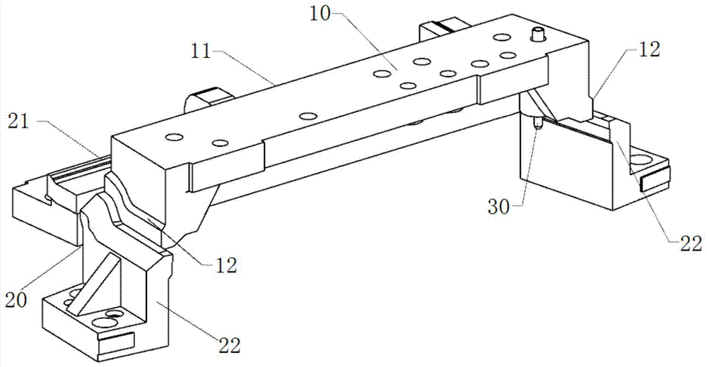
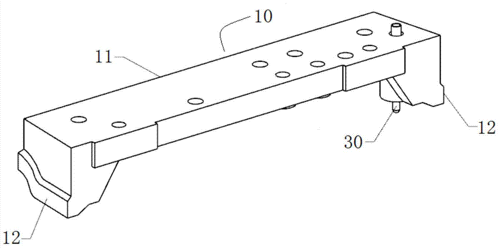
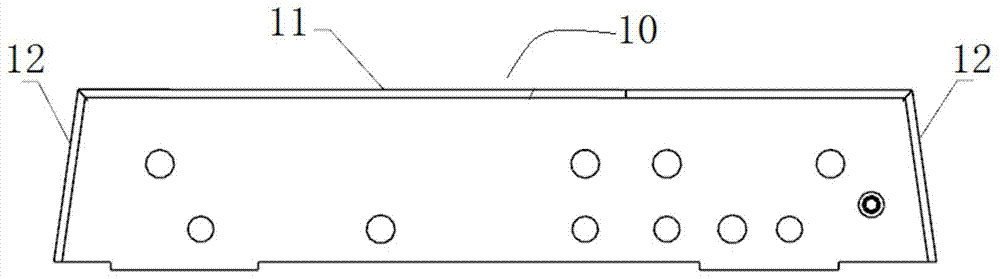
[0025] Such as figure 1 As shown, a waste automatic discharge device described in this embodiment includes an upper die trimming insert 10 and a lower die insert set 20 matched with the upper die trimming insert 10, the upper die trimming The edge insert 10 includes a horizontally placed upper plate 11 and two opposite upper mold waste knives 12 positioned on the side of the upper plate 11, and the lower mold insert group 20 includes a lower mold trimming located below the upper plate 11 The insert 21 and the lower mold scrap knife 22 that is positioned at the side of the lower mold trimming insert 21 and is opposite to the upper mold scrap knife 12, and the edge of the upper mold scrap knife 12 is aligned with the lower mold scrap knife 22 The edge is matched for cutting waste, the angle formed by the edge of the upper die waste knife 12 and the edge of the upper plate 11 and the edge of the lower die waste knife 22 and the edge of the lower die trimming insert 21 The angles...

Embodiment 2

[0032] The present invention also provides a waste material discharge method using any one of the waste automatic discharge devices described above, including the following steps: Step S1: the upper mold trimming insert 10 moves vertically downward until the upper mold waste material The knife 12 cooperates with the waste knife 22 of the lower mold to complete the waste cutting; step S2: the upper mold trimming insert 10 continues to move downward and automatically discharges the waste when it stops; step S3: the upper mold trimming insert After the block 10 moves vertically upwards until it stops again, it repeats from step S1.

[0033] In the waste material discharging method described in the present invention, the waste material automatic discharge device described in any one of the above is used, since the upper mold trimming insert 10 is arranged on the upper mold base, and the lower mold insert group 20 is arranged on the lower mold base In the above, the upper mold base...


PUM


Abstract

The invention relates to an automatic discharge device and method for waste materials, comprising an upper mold trimming insert and a lower mold insert set, the upper mold trimming insert includes an upper plate and an upper mold waste knife, and the lower mold insert The set includes the trimming insert of the lower mold and the scrap knife of the lower mold, and the edge of the scrap knife of the upper mold is matched with the edge of the scrap knife of the lower mold for cutting waste, and the edge of the scrap knife of the upper mold is matched with the edge of the upper plate The angle formed by the mouth and the angle formed by the waste knife edge of the lower mold and the trimming insert edge of the lower mold are all obtuse angles. The waste material automatic discharge device and discharge method of the present invention solve the problem that the waste material slides when the waste knife blades face each other, and is easy to process and manufacture, reduces the probability of technicians having safety problems during debugging, and improves production efficiency.

Description

technical field [0001] The invention relates to a stamping die, in particular to a device and method for automatically discharging waste when the edges of a trimming die's waste knives face each other. Background technique [0002] In recent years, with the development of high technology and the promotion and application of emerging technologies, the mold industry has developed rapidly, especially the stamping mold has reached an unprecedented level, and various new stamping processes and new mold structures emerge in endlessly. However, in the stamping process of the existing trimming die, when the edge of the trimming die waste knife is facing each other, there will be problems such as material jamming or waste sliding down smoothly, which will lead to a reduction in stamping production efficiency. In order to overcome the above problems, technology is usually deployed in the workshop. On-site commissioning by personnel, in the process of on-site commissioning, not only ha...

Claims


Application Information

Patent Timeline
Patent Type & Authority Patents(China)
IPC IPC(8): B21D45/02B21D28/14
Inventor 刘志华李树新张明扬孙莹
Owner BEIQI FOTON MOTOR CO LTD
Why Eureka
Try Eureka