Amphibious Vehicle Lift Wheel Drag Reduction Device

A technology of drag reduction device and lift wheel, which is applied in mechanical gear transmission, transportation and packaging, hydrodynamic characteristics/hydrostatic characteristics, etc. The effect of increasing the speed

Inactive Publication Date: 2017-04-05
SHANGHAI UNIV
View PDF6 Cites 0 Cited by
  • Summary
  • Abstract
  • Description
  • Claims
  • Application Information

AI Technical Summary

Problems solved by technology

However, the current drag reduction devices for amphibious vehicles are generally large in size and cannot effectively utilize the power of the amphibious vehicle itself

Method used


Image

  • Amphibious Vehicle Lift Wheel Drag Reduction Device
  • Amphibious Vehicle Lift Wheel Drag Reduction Device
  • Amphibious Vehicle Lift Wheel Drag Reduction Device

Examples


Embodiment 1

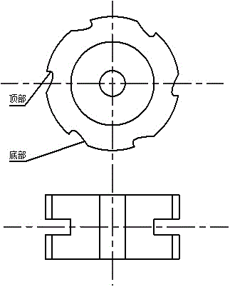
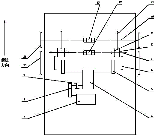
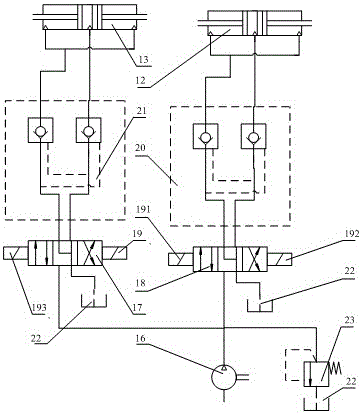
[0019] Such as Figure 1 to Figure 7 As shown, a lift wheel drag reduction device for amphibious vehicles includes two lift wheels 14, a gear transmission mechanism, and a hydraulic control system; The wheel side reducer 5 is connected, and the drive shaft gear 6 is installed on the output shaft of the wheel side reducer 5, and the driving wheel 15 is coaxially installed; the gear transmission mechanism includes two lift wheel shaft gears 11, two lift wheel shafts 10 , two intermediate shafts 7, two intermediate shaft outer end gears 8, two intermediate shaft inner end gears 9, two driving shaft gears 6; two lifting force wheel shaft gears 11 are installed on the two lift wheel shafts 10, and simultaneously Two lifting wheels 14 are installed on the shaft, and an intermediate shaft outer end gear 8 and an intermediate shaft inner end gear 9 are respectively installed on each intermediate shaft 7; the hydraulic control system includes a hydraulic pump 16, the first valve seat 1...

Embodiment 2

[0023] This embodiment is basically the same as Embodiment 1, especially in that, see Figure 1-Figure 7 When the amphibious vehicle enters the water from the land, the third electromagnetic coil 192 is activated to connect the right position of the first valve seat 18 to the hydraulic circuit, the right one-way valve of the first hydraulic lock 20 is connected, and the piston rod of the double-acting middle hydraulic cylinder 12 is extended. Out, the gear 8 at the outer end of the intermediate shaft meshes with the gear 6 of the drive shaft, and at the same time, the inner gear 9 of the intermediate shaft meshes with the gear 11 of the lift wheel shaft, and the lift wheel rotates. Body balance, start the first electromagnetic coil 19, the right position of the second valve seat 17 is connected to the hydraulic circuit, the right one-way valve of the second hydraulic lock 21 is connected, and the double-acting lift wheel hydraulic cylinder 13 enters the rodless cavity, double-a...


PUM


Abstract

The invention relates to an amphibious vehicle force-lifting wheel resistance reducing device, wherein force-lifting wheels are set at the right side and the left side of the front part of an amphibious vehicle body; the force lifting wheels flows to one side according to Archimedes spiral curve; the bottom curve face is smooth; a bending curve face is set on the top portion; on the whole, the bending curve face is a good streamline in order to make water flow along the surface to the bending curve surface on the top portion without separating as far as possible; the lifting force principle is adopted; when an amphibious vehicle is sailing in the water, the rotation of the force lifting wheels is controlled by utilizing a hydraulic control system and gear transmission mechanism; wings of the wheels is rotated relative to the water; and the whole wheels will produce upward lifting force and forward pushing force, thus increasing the sailing angle of the amphibious vehicle and reducing the draft to reduce resistance while increasing the pushing force; the resistance reduction is realized; and the sailing speed is improved.

Description

technical field [0001] The invention relates to a drag reducing device for an amphibious vehicle, in particular to a drag reducing device for a lift wheel of an amphibious vehicle. Background technique [0002] Amphibious vehicles are capable of both land propulsion and water navigation, and are suitable for various working conditions, so they have been widely studied and applied. The rapidity of the vehicle is one of the important performances of the vehicle. In the design and manufacture of the vehicle, reaching the rapidity index can not only meet the speed requirements proposed in the design task book, but also ensure the economic and social efficiency of the vehicle. Experiments have proved that when navigating in water, the resistance suffered by the amphibious vehicle increases with the increase of the draft of the vehicle body. However, the current drag reduction devices for amphibious vehicles are generally bulky and cannot effectively utilize the power of the amph...

Claims


Application Information

Patent Timeline
Patent Type & Authority Patents(China)
IPC IPC(8): B63B1/40B63B1/16B63H23/04
CPCY02T70/10
Inventor 何斌周高飞张鹏昌顾卓超汤文
Owner SHANGHAI UNIV
Why Eureka
Try Eureka