Fabric drum shaft conveying device

A technology of cloth reel shaft and conveying device, which is applied in the direction of conveyor control device, conveyor, conveyor objects, etc., can solve the problems of increasing manual labor, trouble in handling, etc., and achieve the effect of reducing manual labor and convenient transportation.

Active Publication Date: 2015-08-26
启东市固德防水布有限公司
View PDF5 Cites 20 Cited by
  • Summary
  • Abstract
  • Description
  • Claims
  • Application Information

AI Technical Summary

Problems solved by technology

[0002] The existing cloth reel shaft needs to be transported, and the existing transportation method is through manual handling or by placing the cloth reel shaft on the conveyor belt for transportation and transportation. When the location is relatively long, it needs to be transported by two conveyor belts, and the two conveyor belts are on the same straight line, and manual handling is required between the two conveyor belts, which is very troublesome and increases the amount of manual labor.

Method used


Image

  • Fabric drum shaft conveying device
  • Fabric drum shaft conveying device
  • Fabric drum shaft conveying device

Examples


Embodiment Construction

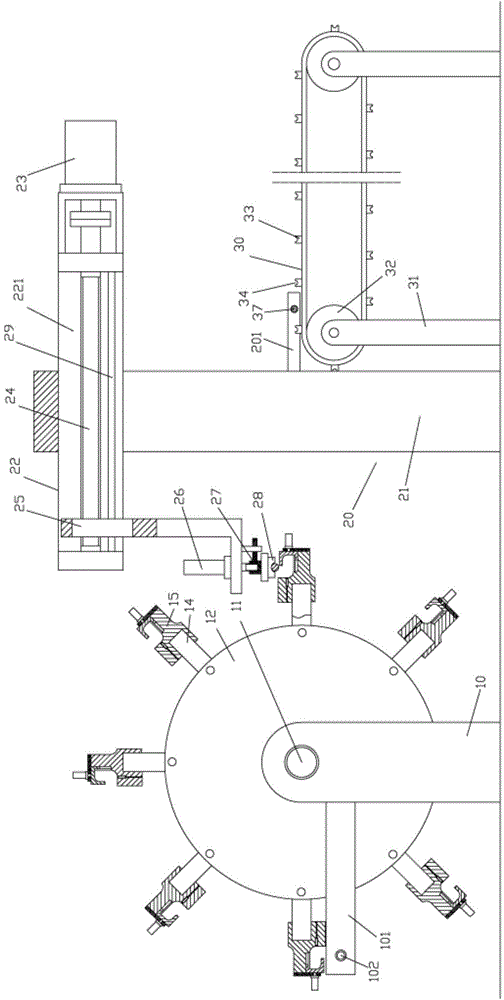
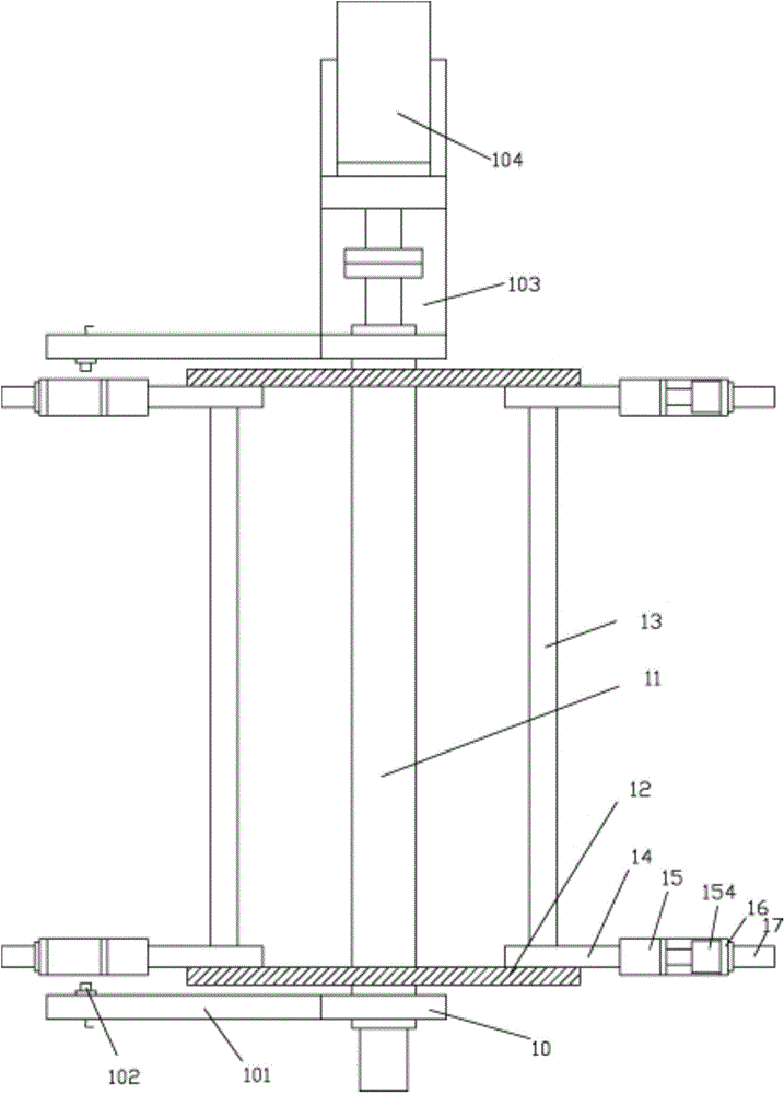
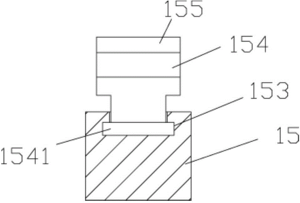
[0024] Example: see Figures 1 to 6 As shown, a cloth reel shaft conveying device includes a connecting bracket 10, a conveyor belt 30 and an extraction support frame 20. The connecting bracket 10 is hinged at the two ends of the middle rotating shaft 11, and the connecting bracket 10 is fixed on the ground. Two circular discs 12 are fixed on the rotating shaft 11, and the two ends of a plurality of transverse connecting rods 13 are respectively fixed on the corresponding circular discs 12, and all transverse connecting rods 13 are evenly distributed on both sides with the intermediate rotating shaft 11 as the central axis. On a circular disc 12, a grabbing arm 14 is fixed on the transverse connecting rod 13, and the grabbing block 15 is fixed on the end of the grabbing arm 14, and the extraction support frame 20 is fixed on the front bottom surface of the connection bracket 10, and the extraction support frame The front portion of 20 is fixed with driving roller support frame...


PUM


Abstract

The invention discloses a fabric drum shaft conveying device which comprises connecting supports, conveying belts and extracting supporting frames. The connecting supports are hinged to the two ends of a middle rotating shaft and fixed on the ground, two round discs are fixed on the middle rotating shaft, the two ends of a plurality of horizontal connecting rods are fixed on the corresponding round discs respectively, all the horizontal connecting rods are evenly distributed on the two round discs with the middle rotating shaft as a center shaft, capturing arms are fixed on the horizontal connecting rods, capturing blocks are fixed at the ends of the capturing arms, the extracting supporting frames are fixed on the bottom surfaces of the front of the connecting supports, transmission roller supporting frames are fixed in the front of the extracting supporting frames, two transmission rollers are hinged to the corresponding transmission roller supporting frames, the conveying belts are tensioned between the two transmission rollers, and fabric drum shaft placing blocks are fixed on the two sides of outer walls of the conveying belts. The fabric drum shaft conveying device can automatically carry fabric drum shafts on one conveying belt to another conveying belt, have convenience in carrying and reduce labor amount.

Description

Technical field: [0001] The invention relates to the technical field of textile equipment, in particular to a cloth reel shaft conveying device. Background technique: [0002] The existing cloth reel shaft needs to be transported, and the existing transportation method is through manual handling or by placing the cloth reel shaft on the conveyor belt for transportation and transportation. When the position is relatively long, it needs to be transported by two conveyor belts, and the two conveyor belts are on the same straight line, and manual handling is required between the two conveyor belts, which is very troublesome to carry and increases the amount of manual labor. Invention content: [0003] The purpose of the present invention is to address the deficiencies in the prior art, and provide a cloth reel shaft conveying device, which can automatically transfer the cloth reel shaft on one conveyor belt to another, which is convenient to carry and reduces the amount of man...

Claims


Application Information

Patent Timeline
Patent Type & Authority Applications(China)
IPC IPC(8): B65G47/52B65G47/64B65G47/91
CPCB65G15/58B65G43/08B65G47/52B65G47/64B65G47/644B65G47/647B65G47/847B65G47/904B65G47/92
Inventor 谈星
Owner 启东市固德防水布有限公司
Why Eureka
Try Eureka