Magnetic flywheel for sewing machine

A sewing machine and magnetic suction technology, applied in the field of flywheel, can solve the problems of small flywheel and small penetrating power, and achieve the effect of small kinetic energy, increased penetrating power and simple structure

Active Publication Date: 2017-09-01
WUJIANG ZHENYU SEWING EQUIP
View PDF6 Cites 0 Cited by
  • Summary
  • Abstract
  • Description
  • Claims
  • Application Information

AI Technical Summary

Problems solved by technology

[0003] The flywheels of traditional sewing machines are designed to be relatively small, because the kinetic energy provided is relatively small, and the penetration force when encountering resistance is relatively small, so it can only be used for some thinner fabrics, so there are great defects

Method used


Image

  • Magnetic flywheel for sewing machine
  • Magnetic flywheel for sewing machine

Examples


Embodiment Construction

[0013] In order to deepen the understanding of the present invention, the present invention will be described in further detail below in conjunction with the accompanying drawings and embodiments, which are only used to explain the present invention and do not limit the protection scope of the present invention.

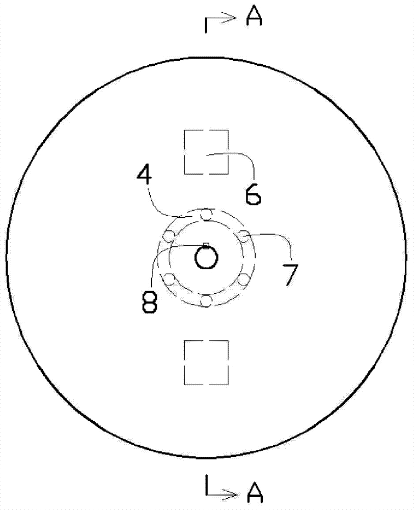
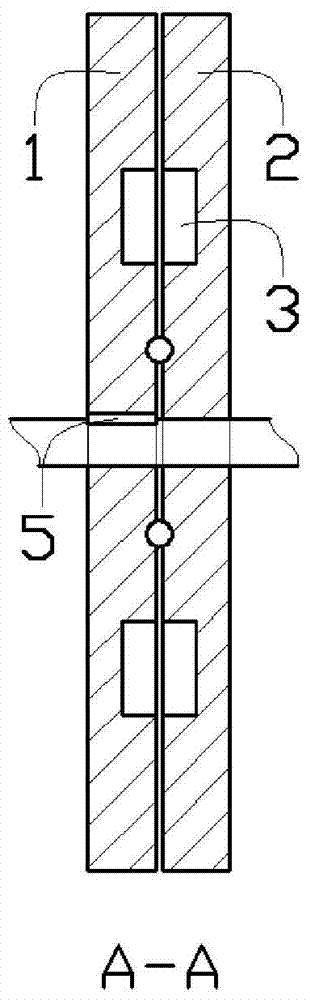
[0014] Such as figure 1 As shown, a sewing machine magnetic suction flywheel, which includes a driving rotating wheel 1, a driven rotating wheel 2, a square magnet 6, a ball 7 and a positioning pin 8; the front surface of the driving rotating wheel 1 is designed with two symmetrical A square groove 3 and an annular groove 4, the central hole of the driving rotating wheel 1 is designed with a keyway 5; the rear surface of the driven rotating wheel 2 is designed with a square groove 3 and an annular groove 4 corresponding to the front surface of the driving rotating wheel, The driven rotating wheel 2 is rotatably assembled on the main shaft; the shape and size of the s...


PUM


Abstract

The invention discloses a magnetically-attractive fly wheel of a sewing machine and relates to the field of sewing machinery. The problem that the fly wheel size cannot be changed is solved. The magnetically-attractive fly wheel of sewing machine comprises a driving rotation wheel, a driven rotation wheel, a square magnet, a rolling ball and a positioning pin. Two square grooves symmetrical with respect to the circle center and an annular groove are designed in the front surface of the driving rotation wheel and the driven rotation wheel correspondingly, and a key groove is designed in a central hole of the driving rotation wheel. The driven rotation wheel is rotatably assembled on a spindle. The square magnet is fixedly installed in the square groove. The positioning pin is fixedly installed on the spindle and the key groove formed in the driving rotation wheel and drives the driven rotation wheel to rotate through the magnet, the weight of the whole fly wheel is increased to increase kinetic energy stored by the fly wheel and further increase penetrating power while the sewing machine slowly provides kinetic energy, and instant overlarge load is not brought to the machine.

Description

technical field [0001] The invention relates to the field of sewing machines, in particular to a flywheel. Background technique [0002] The flywheel is a disc-shaped part with a large moment of inertia, which acts as an energy storage; for common household sewing machines, the handwheel driven by the belt at the head of the sewing machine is the flywheel. The larger the flywheel, the more kinetic energy it stores during sewing. Large, so it can penetrate when encountering relatively large resistance. [0003] The flywheels of traditional sewing machines are designed to be relatively small, because the kinetic energy provided is relatively small, and the penetration force when encountering resistance is relatively small, so it can only be used for some thinner fabrics, so there are great defects. Contents of the invention [0004] In order to solve the above technical problems, the present invention provides a sewing machine magnetic flywheel. [0005] The technical sche...

Claims


Application Information

Patent Timeline
Patent Type & Authority Patents(China)
IPC IPC(8): D05B69/30
CPCD05B69/30
Inventor 胡粉义
Owner WUJIANG ZHENYU SEWING EQUIP
Why Eureka
Try Eureka