Hollow buffer driving device

A buffer drive, hollow technology, applied in the direction of fluid pressure actuation device, injection device, pipeline support, etc., can solve the problems of exposure to the external environment and complex overall structure.

Active Publication Date: 2015-08-26
SCIENTECH
View PDF5 Cites 0 Cited by
  • Summary
  • Abstract
  • Description
  • Claims
  • Application Information

AI Technical Summary

Problems solved by technology

However, in this prior art, on the one hand, the delivery pipeline 1090B is easily exposed to the

Method used


Image

  • Hollow buffer driving device
  • Hollow buffer driving device
  • Hollow buffer driving device

Examples


Embodiment Construction

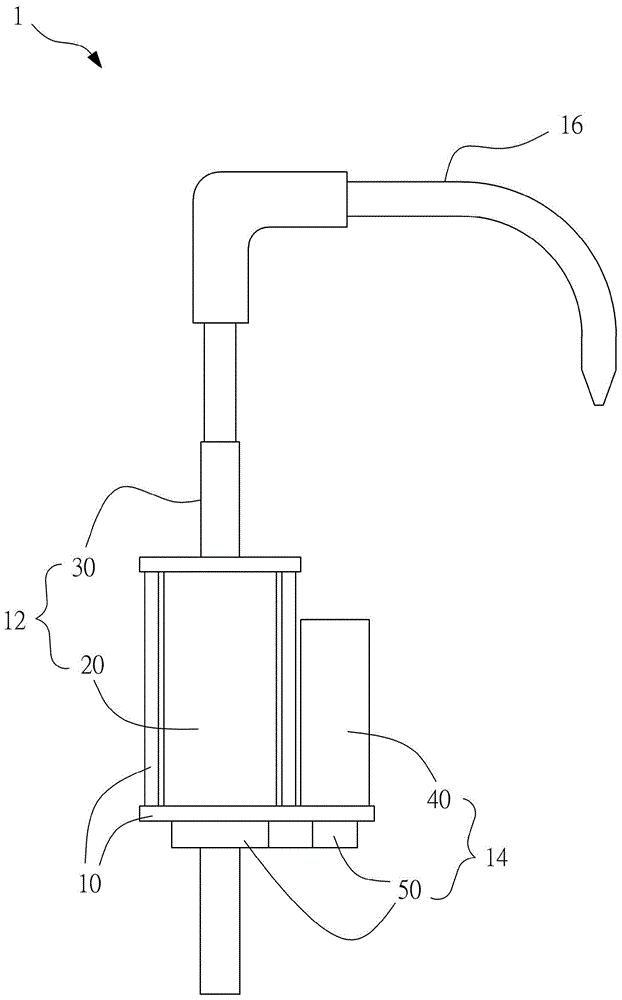
[0067] Please refer to figure 1 , which shows a perspective view of a hollow buffer driving device 1 according to an embodiment of the present invention. The hollow buffer driving device 1 includes a base 10 , a lift mechanism unit 12 , a rotation mechanism unit 14 , and a pipeline support unit 16 . Wherein, the lifting mechanism unit 12 is rotatably mounted on the base 10 ; the rotating mechanism unit 14 is mounted on the base 10 for rotating the lifting mechanism unit 12 ; the pipeline support unit 16 is mounted on the lifting mechanism unit 12 .

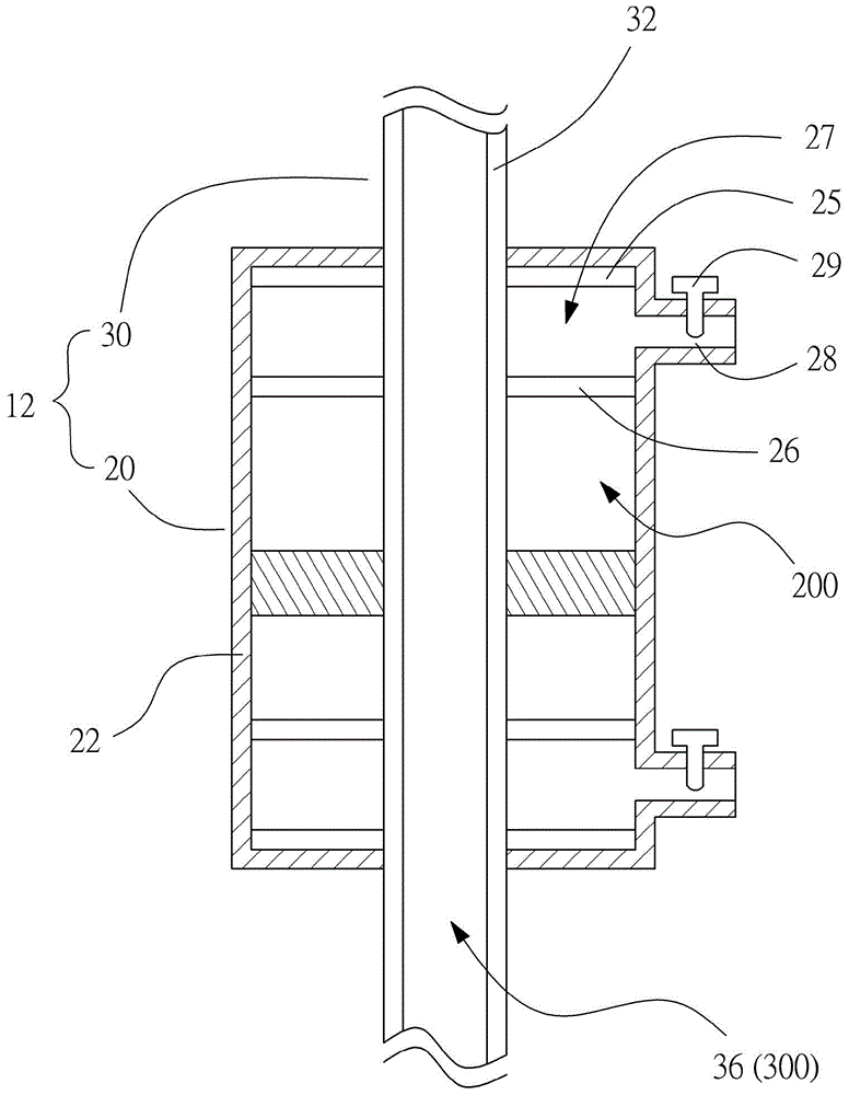
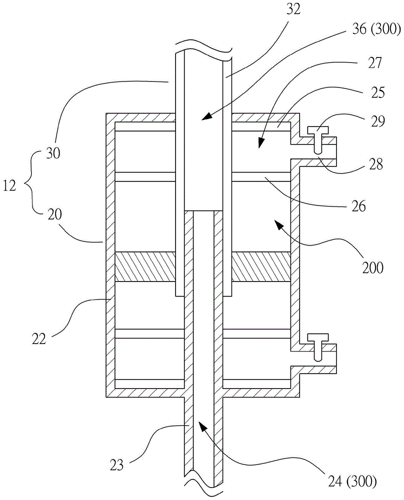
[0068] Please refer to Figure 2A , which shows a cross-sectional view of the lifting mechanism unit 12 according to an embodiment of the present invention. Lifting mechanism unit 12 has a cylinder body 20 and a piston rod 30; Cylinder body 20 has a housing 22, and housing 22 limits a cylinder body space 200; Piston rod 30 has a handle 32 and a head 34, handle 32 is hollow to define a handle space 36, and is worn through the t...


PUM


Abstract

The present invention provides a hollow buffer driving device, comprising a lifting mechanism unit having a cylinder body and a piston rod, wherein the cylinder body has a housing which defines a cylinder body space, the piston rod has a handle part and a head part, the handle part is hollow so as to define a handle part space, and penetrates one end or two ends of the housing, the head part is fixedly connected to the handle part, and is arranged in the cylinder body space. Through the hollow design of the handle part of the piston rod of the lifting mechanism unit, the integral construction of the hollow buffer driving device is simpler and tighter.

Description

【Technical field】 [0001] The present invention relates to an adjustment device, in particular to a hollow buffer driving device which is used for installing a delivery pipeline for delivering fluid and can adjust the outlet of the delivery pipeline to a target position, which can be applied to semiconductor wafers, The manufacturing process of flat substrates such as solar substrates, display glass substrates, LED substrates, etc., but not limited to these processes, and when using different chemicals in the manufacturing process for single-chip rotary etching, cleaning, drying, etc., carry liquid or gas supply To the top of the substrate, cooperate with the program-controlled lifting or left-right rotation coating or spraying mechanism. 【Background technique】 [0002] In the prior art, there are already many adjusting devices for fitting the conveying pipeline therein, and spraying the processing fluid in the conveying pipeline to the workpiece as required. However, these ...

Claims


Application Information

Patent Timeline
IPC IPC(8): F16L3/16F16L57/00F15B15/22B05B15/68
CPCF15B15/22F16L3/16F16L57/00
Inventor 刘茂林
Owner SCIENTECH
Why Eureka
Try Eureka