A surge current test circuit with built-in detection function

A surge current and test circuit technology, which is applied in the field of semiconductor device detection, can solve problems such as time-consuming, difficult, safety and reliability effects, and achieve the effects of improving work efficiency, facilitating inspection, and avoiding repeated testing

Active Publication Date: 2017-06-06
SHANDONG JINGDAO MICROELECTRONICS
View PDF7 Cites 0 Cited by
  • Summary
  • Abstract
  • Description
  • Claims
  • Application Information

AI Technical Summary

Problems solved by technology

[0002] With the development of mobile information products, household electrical appliances, and green lighting, a large number of diode devices such as rectifier bridges, diodes, and voltage regulators have been used in their supporting electronic products, and the "light, thin Higher requirements are put forward for "small, small and dense". At present, rectifier diode products, which are the most widely used diode devices, are also developing in the direction of integration. Safety and reliability have a great impact. It is time-consuming and difficult to detect the maximum value of surge current as a parameter to measure the ability of diode devices to resist forward current impact. Reliability research and quality improvement are very important. Existing equipment can only set the standard value current to detect this parameter, and then use other equipment to detect whether the device fails after the impact surge is triggered. To find out the current capability limit is Difficult things often require a lot of trial and error

Method used


Image

  • A surge current test circuit with built-in detection function
  • A surge current test circuit with built-in detection function
  • A surge current test circuit with built-in detection function

Examples


Embodiment Construction

[0022] In order to facilitate those skilled in the art to better understand the present invention, the present invention will be described in further detail below in conjunction with the accompanying drawings and specific embodiments. The following is only exemplary and does not limit the protection scope of the present invention.

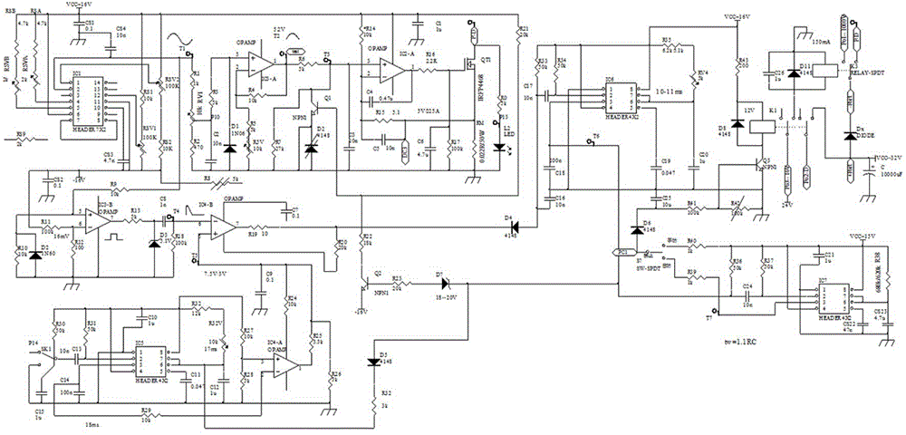
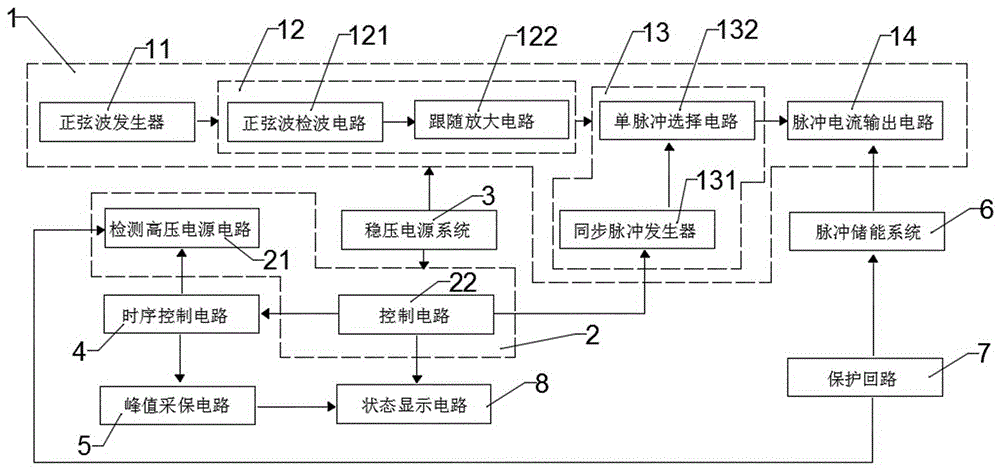
[0023] like figure 1 As shown, the surge current test circuit with its own detection function in the present invention includes a surge current trigger circuit 1, a detection control circuit 2 for detecting diode devices after the surge current is triggered, a stabilized power supply system 3, and a sequence control circuit Circuit 4, peak value acquisition and protection circuit 5, pulse energy storage system 6, protection circuit 7 and status display circuit 8, regulated power supply system 3 provides regulated power supply for surge current trigger circuit 1 and detection control circuit 2. The surge current trigger circuit 1 includes a sine wav...


PUM


Abstract

The invention discloses a surge current testing circuit with a function of detection, and the circuit comprises a surge current triggering circuit, a detection control circuit for detecting diode-type devices after surge current triggering, a stabilized-voltage power system, a time sequence control circuit, and a peak value sampling protection circuit. The stabilized-voltage power system supplies a stabilized-voltage power supply to the surge current triggering circuit and the detection control circuit. The detection control circuit comprises a high-voltage power detection circuit and a control circuit, wherein the control circuit respectively controls a synchronizing pulse generator, and controls the high-voltage power detection circuit and the peak value sampling protection circuit through the time sequence control circuit. The circuit provided by the invention can automatically detect the condition of a device after surge currents are triggered, and also can judge the polarity of the diode-type devices. The arrangement of different surge currents enables the maximum value of a surge current withstood by the diode-type devices to be quickly detected, thereby facilitating the detection, comparison and analysis of products. The circuit avoids repeated testing, and improves the work efficiency.

Description

technical field [0001] The invention relates to a surge current test circuit with a self-contained detection function, which belongs to the technical field of semiconductor device detection. Background technique [0002] With the development of mobile information products, household electrical appliances, and green lighting, a large number of diode devices such as rectifier bridges, diodes, and voltage regulators have been used in their supporting electronic products, and the "light, thin Higher requirements are put forward for "small, small and dense". At present, rectifier diode products, which are the most widely used diode devices, are also developing in the direction of integration. Safety and reliability have a great impact. It is time-consuming and difficult to detect the maximum value of surge current as a parameter to measure the ability of diode devices to resist forward current impact. Reliability research and quality improvement are very important. Existing equi...

Claims


Application Information

Patent Timeline
Patent Type & Authority Patents(China)
IPC IPC(8): G01R31/26
Inventor 贺先忠孔凡伟段花山贾林夏金龙刘君
Owner SHANDONG JINGDAO MICROELECTRONICS
Why Eureka
Try Eureka