Eureka AIR delivers breakthrough ideas for toughest innovation challenges, trusted by R&D personnel around the world.

Room temperature shim coil of superconducting NMR spectrometer

A technology of nuclear magnetic resonance spectroscopy and shim coils, which is applied to instruments, measuring magnetic variables, measuring devices, etc., can solve the problems of poor adaptability of shim coils, inability to solve high-order terms, and single structure of shim coils.

Active Publication Date: 2015-08-26
ウーハン ジョンケ ニウジン マグネティック レゾナンス テクノロジー カンパニー リミテッド
View PDF2 Cites 19 Cited by
  • Summary
  • Abstract
  • Description
  • Claims
  • Application Information

AI Technical Summary

Problems solved by technology

[0003] At present, the structure of shim coils in the prior art is relatively simple, and the space utilization rate is not high, and some algorithms are proposed for the design of the above-mentioned existing shim coils, for example, the flow function and the target field method are used as shimming The theoretical basis of the coil design algorithm, and the use of Maxwell equations to obtain theoretical values ​​to solve high-order terms, but the above-mentioned prior art still has the following problems: (1) the flow function and the target field method do not use practical shim coils as the design (2) For the Maxwell equation, for a superconducting NMR spectrometer that requires 28 or even 40 sets of coils, the high number of methods makes the equation more complex, and it is almost impossible to solve the high-order terms; ( 3) The above design algorithm is not very adaptable to shim coils, it is only suitable for Halbach magnets with cylindrical magnet cavity and transverse magnetic field, and cannot meet the requirements of superconducting NMR spectrometers for three-dimensional magnetic fields in more complex spaces

Method used

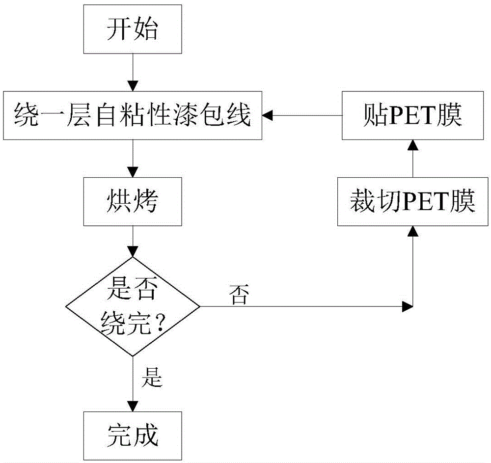
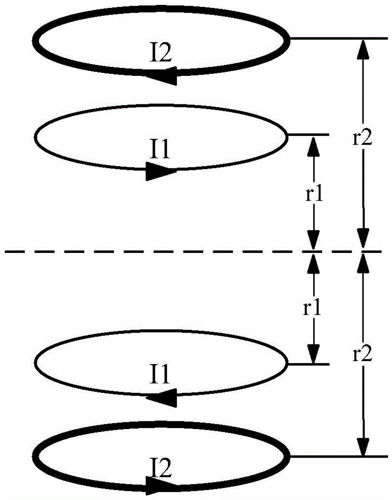

Image

  • Room temperature shim coil of superconducting NMR spectrometer
  • Room temperature shim coil of superconducting NMR spectrometer
  • Room temperature shim coil of superconducting NMR spectrometer

Examples


Embodiment Construction

[0043] In order to make the object, technical solution and advantages of the present invention clearer, the present invention will be further described in detail below in conjunction with the accompanying drawings and embodiments. It should be understood that the specific embodiments described here are only used to explain the present invention, not to limit the present invention. In addition, the technical features involved in the various embodiments of the present invention described below can be combined with each other as long as they do not constitute a conflict with each other.

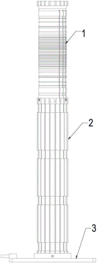
[0044] The room temperature shim coil involved in this embodiment is as figure 1 As shown, the room temperature shim coil consists of a winding area 1 , a support frame 2 and a base 3 from top to bottom. The winding area 1 is located at the uppermost end, the support frame 2 is in the middle, and the base 3 is at the lower end. The inner layer of the winding area 1 used in this embodiment is a...


PUM


Abstract

The invention discloses a room temperature shim coil of a superconducting NMR spectrometer. The room temperature shim coil is formed by a winding region, a support frame, and a base from top to bottom in sequence. The inner layer of the winding region is axial coils, and the outer layer is radial coils. On the manufacturing method for a coil structure, the multiple order axial coils are compressed on a same cylinder to improve space utilization rate, and a winding method of self-bonding enamelled wires and PET films (also named as high-temperature polyester film) is used, so as to solve technical problems of wire positioning and fixing in a winding process of the room temperature shim coil. An optimization function is also designed and established aimed at an algorithm of the shim coil, and a problem of design of the room temperature shim coil is converted to a problem of solving the minimum value of the optimization function, and then through a particle swarm optimization, the functional equation is solved, and finally position distribution and number of turns of the coils can be calculated. According to the room temperature shim coil, reliability and adaptability of the shim coil can be obviously improved.

Description

technical field [0001] The invention belongs to the field of nuclear magnetic resonance spectrometers, and more specifically relates to a room-temperature shim coil of a superconducting nuclear magnetic resonance spectrometer. Background technique [0002] In a superconducting NMR spectrometer, the uniformity of the spatial magnetic field directly affects the quality of the collected spectra. In order to improve the uniformity of the magnetic field, technicians should not only do low-temperature superconducting shimming when the magnet is rising, but also Do room temperature shimming after the field, the current method of room temperature shimming is to install room temperature shimming coils in the magnet of the nuclear magnetic resonance spectrometer, and the shimming coils of each order will generate compensation magnetic fields of different shapes and sizes under the drive of the magnetron current. , these compensating magnetic fields together cancel out the non-constant...

Claims


Application Information

Patent Timeline
IPC IPC(8): G01R33/3875
CPCG01R33/3875G01R33/3815
Inventor 陈康
Owner ウーハン ジョンケ ニウジン マグネティック レゾナンス テクノロジー カンパニー リミテッド
Why Eureka
Eureka Blog
Learn More