Wire Twisting Fixtures, Twisting Machines and Twisting Systems

A wire twisting machine and wire twisting technology, which is applied in the field of wire twisting machines, wire twisting systems, and wire foot twisting fixtures. It can solve the problems of workers' hand strain, wire feet re-separation, and the inability to apply torque evenly to the wire feet, so as to reduce labor intensity. , prevent re-separation, and realize the effect of mechanization

Active Publication Date: 2016-09-21
佛山市华葆电源设备有限公司
View PDF7 Cites 0 Cited by
  • Summary
  • Abstract
  • Description
  • Claims
  • Application Information

AI Technical Summary

Problems solved by technology

This manual processing method is easy to strain the hands of workers; at the same time, because the process of manual twisting cannot achieve uniform torque on the wire feet, the stress accumulation will occur in the wire feet twisted into one strand. There will be a phenomenon of re-separation of the stitches in the processed stitch group

Method used


Image

  • Wire Twisting Fixtures, Twisting Machines and Twisting Systems
  • Wire Twisting Fixtures, Twisting Machines and Twisting Systems
  • Wire Twisting Fixtures, Twisting Machines and Twisting Systems

Examples


Embodiment 1

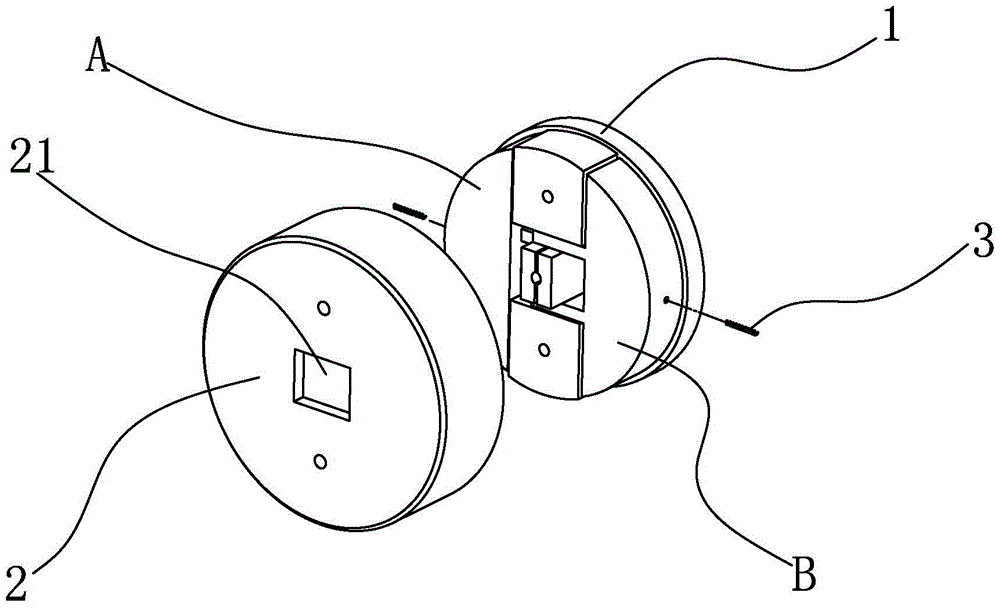
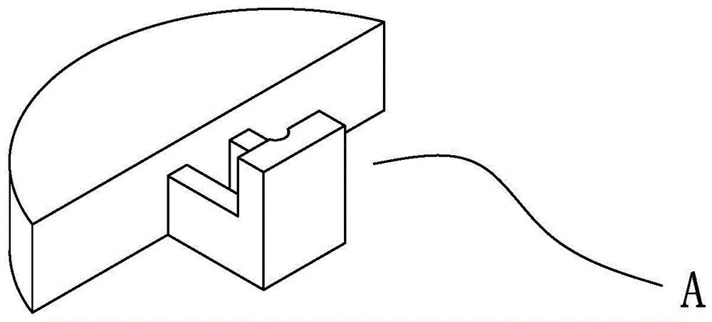
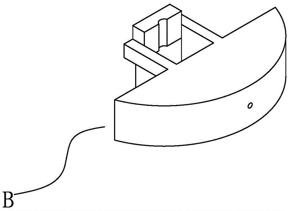
[0024] Such as Figure 1~4 As shown, a wire twisting clamp includes a clamp base 1 , a cover body 2 , a clamping block A, a clamping block B, and a return spring 3 . The clamp base 1 is circular and can rotate around the central axis. Two connecting columns are symmetrically arranged on the clamp base 1 with respect to the central axis. The cover 2 is fixedly connected to the clamp base 1 through the connecting columns. A cavity is formed between the clamp seat 1 and the cover body 2 , and an opening 21 is provided at the intersection of the surface of the cover body 2 and the central axis for inserting the wire legs into the cavity. The clamping block A and the clamping block B are symmetrically arranged in the cavity with respect to the central axis, and can slide and reset in the radial direction. Clamp A and clamp B are both equipped with a counterweight and a clamping body, the clamping body is connected with the counterweight through a connecting rod, the clamping body ...

Embodiment 2

[0026] A thread leg twisting fixture includes a fixture seat, a clamping block C, a clamping block D, a clamping block E, and a return spring. The clamp seat is in the shape of a regular hexagon, and the clamp blocks C, D, E are arranged on the clamp seat at intervals of 120° around the central axis, and are provided with a clamping body and a trapezoidal counterweight. The counterweights are arranged at intervals of 180° around the central axis, and the clamping body and the counterweights are connected through connecting rods. The clamp seat is provided with a guardrail on the bottom edge of each counterweight body to prevent the clamp block from falling off, and the return spring is arranged between the counterweight body and the guardrail. All the other designs are the same as in Example 1.

[0027] A wire twisting machine, comprising a frame, the upper surface of the frame is provided with the wire leg twisting fixture as described above, the frame is provided with a mot...


PUM


Abstract

The invention discloses a wire end twisting clamp. The wire end twisting clamp includes a clamp seat which can rotate around a center axis; the clamp seat is provided with more than two clamping blocks which can slide along a radial direction and can be reset; each clamping block comprises a weight-balancing body and a clamping body which are connected with each other; the clamping body and the weight-balancing body are located at two sides of the center axis respectively; one side of the clamping body, which is adjacent to the center axis, is provided with provided with a pressure applying surface which contacts with wire ends; the weight of the weight-balancing body is greater than that of the clamping body; and the clamping bodies of the more than two clamping blocks are engaged with each other with gaps left therebetween. The invention also discloses a wire twisting machine and a wire twisting system. With the wire end twisting clamp, wire twisting machine and wire twisting system of the invention adopted, mechanization of wire end twisting can be realized, and the labor intensity of workers can be reduced, and the working efficiency of wire end group processing can be improved, and a wire end group can be prevented from being split due to stress accumulation. The wire end twisting clamp, wire twisting machine and wire twisting system of the invention can be applied to twisting wire ends into a wire end group.

Description

technical field [0001] The invention relates to special equipment for twisting conductors or cables, in particular to a wire leg twisting fixture, a twisting machine and a twisting system using the same. Background technique [0002] In industrial manufacturing, it is often necessary to twist the legs of multi-strand wires into one strand to realize parallel or series connection of equipment circuits. In the actual production process, the worker strips the insulation layer of the wire port, and then twists the exposed wire legs together by hand or hand-held iron pliers. This manual processing method is easy to strain the hands of workers; at the same time, because the process of manual twisting cannot achieve uniform torque on the wire feet, the stress accumulation will occur in the wire feet twisted into one strand. There will be a phenomenon of re-separation of the stitches in the processed stitch group. Contents of the invention [0003] The technical problem to be so...

Claims


Application Information

Patent Timeline
Patent Type & Authority Patents(China)
IPC IPC(8): H01B13/02
Inventor 周伟文林小琴封宁波尹晓娟李静静钟立亮聂文强
Owner 佛山市华葆电源设备有限公司
Why Eureka
Try Eureka