Solder strip shaping mechanism

A technology of welding ribbon and clamping mechanism, applied in sustainable manufacturing/processing, electrical components, climate sustainability, etc., can solve the problems of low photoelectric conversion efficiency of cells, high cost of use and maintenance, and complex structure of stringer welding machines, etc. problem, to achieve the effect of simple structure, convenient operation, and increase the secondary utilization of light energy

Active Publication Date: 2015-08-26
WUXI AUTOWELL TECH
View PDF6 Cites 15 Cited by
  • Summary
  • Abstract
  • Description
  • Claims
  • Application Information

AI Technical Summary

Problems solved by technology

[0007] For this reason, the technical problem to be solved in the present invention is to overcome the low photoelectric conversion efficiency of the cells processed by the traditional stringer, and the stringer integrated with the function of sticking the film (the surface of the welding strip with a reflective film) has a complex structure, using, The disadvantages of high maintenance cost and difficult operation, and then provide a ribbon shaping mechanism for stringer welding machines that can improve the utilization rate of light, has a simple structure, is convenient to operate, and has low maintenance costs

Method used


Image

  • Solder strip shaping mechanism
  • Solder strip shaping mechanism
  • Solder strip shaping mechanism

Examples


Embodiment 1

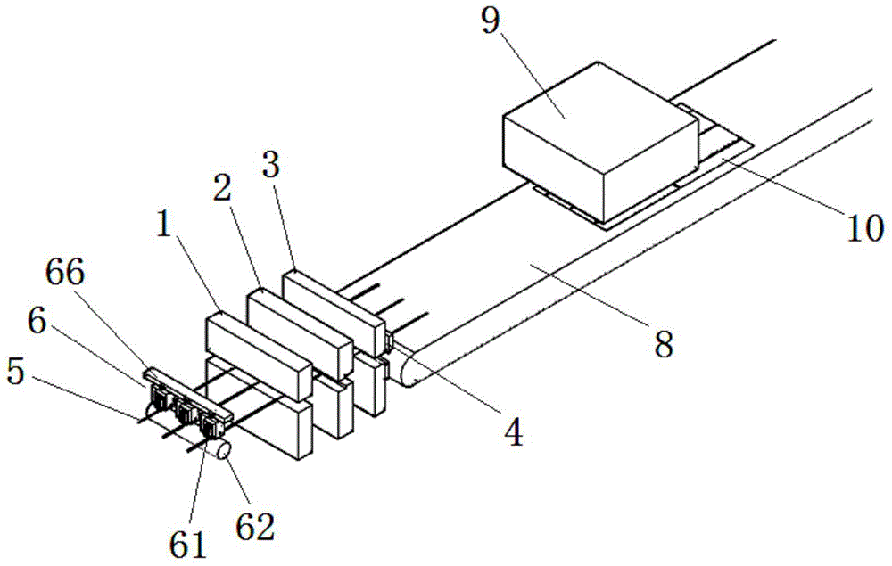
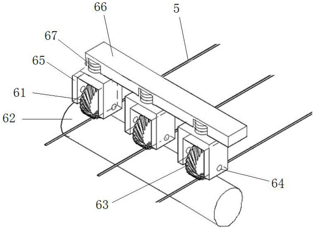
[0029] see Figure 1-2 , a welding ribbon shaping mechanism, which includes a welding ribbon stretching and clamping mechanism 1 arranged in sequence along the conveying direction of the welding ribbon 5, for guiding the welding ribbon 5 from the welding ribbon roll (not shown in the figure) to movement of one side of the weld, i.e. figure 1 Move from left to right in the middle; the ribbon bending mechanism 2 is used to bend the ribbon 5 into a "Z" shape (the "Z" shape mentioned here refers to bending the ribbon into a section to carry the battery The front side of the battery sheet, and the other half is equipped with the reverse side of the adjacent battery sheet) so that two adjacent battery sheets can be connected in series; the cutting and clamping mechanism 3 is used for clamping and fixing the welding ribbon 5 before cutting; the cutter 4 is used for Cutting off the welding ribbon 5 to process a battery string of a predetermined length; between the welding ribbon roll...

Embodiment 2

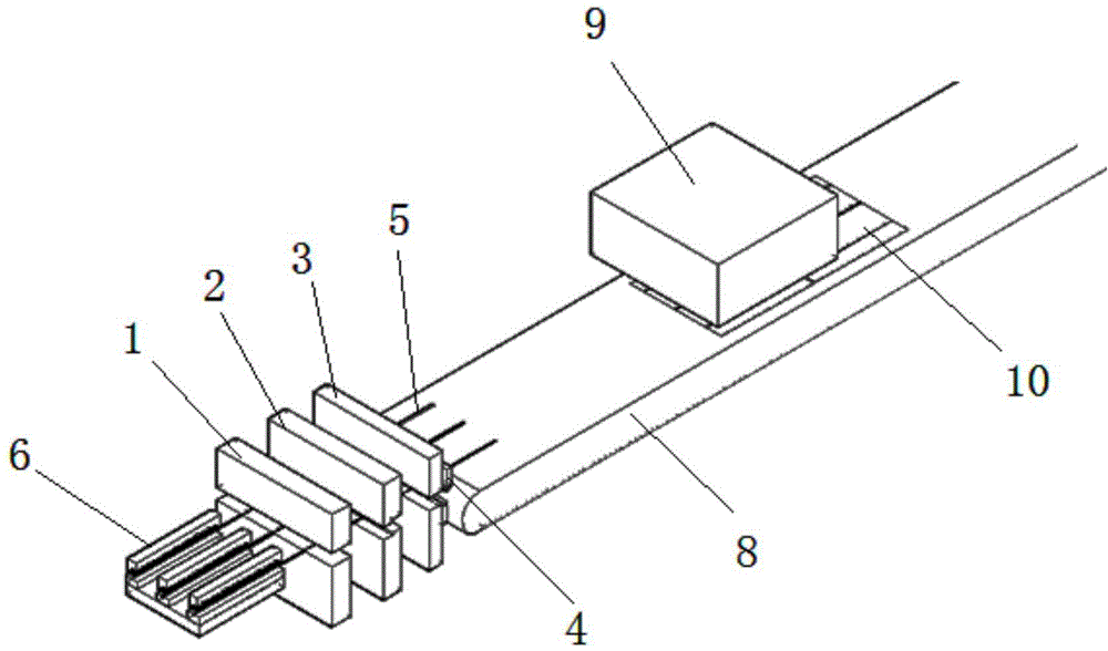
[0035] see Figure 3-4 , on the basis of the above-mentioned embodiment 1, the indentation mechanism 6 in this embodiment is replaced by the following structure:

[0036] The indentation mechanism 6 includes a stamping block 71 and a backing plate 72, the welding ribbon 5 passes between the stamping block 71 and the backing plate 72, and stamping protrusions are arranged on the stamping surface of the stamping block 71 The stamping block 71 can approach or move away from the backing plate 72 driven by the driving mechanism, and the upper surface of the backing plate 72 is a flat surface. When the driving mechanism drives the punching plate 71 to move toward the side close to the backing plate 72, the upper surface of the welding ribbon 5 is embossed with preset indentations; , There will be no dents at the embossed place on the welding strip 5 . This structural design is convenient for pressing required dents at predetermined positions of the welding strip, that is, pressing...


PUM


Abstract

The invention discloses a solder strip shaping mechanism, and the mechanism comprises a solder strip tensioning clamping mechanism, a solder strip bending mechanism, a cutting clamping mechanism, and a cutter, wherein the solder strip tensioning clamping mechanism, the solder strip bending mechanism, the cutting clamping mechanism and the cutter are sequentially arranged along a solder strip conveying direction. A marking press mechanism which is used for forming a pattern for light diffuse reflection on the surface of a solder strip is disposed between a solder strip coil and the cutting clamping mechanism. Compared with a conventional film-pasting mechanism, the mechanism is simpler, is smaller in number of parts, is convenient to operate, is lower in cost of production and maintenance, can improve the effect of light reflection, improves the secondary utilization ratio of light energy, and improves the efficiency of power generation.

Description

technical field [0001] The invention relates to the technical field of photovoltaic module production and manufacturing equipment, in particular to a ribbon shaping mechanism. Background technique [0002] Photovoltaic modules mainly use the solar cells on their surface to absorb sunlight and convert it into electricity. When the components are packaged, the adjacent cells are connected in series through the ribbon, because the surface of the ribbon does not have photoelectric conversion capability, and the ribbon attached to the surface of the cell will block the lighting of the cell and reflect the incoming light , which in turn affects the overall photoelectric conversion efficiency of the module. [0003] Conventional photovoltaic ribbons are tin-plated copper ribbons, which re-solidify on the copper-based surface after soldering and melting of the tin layer, and adhere to the cells. The tin layer formed by re-solidification on the surface of the ribbon has a certain r...

Claims


Application Information

Patent Timeline
IPC IPC(8): H01L31/18B21D21/00
CPCB21D21/00H01L31/18Y02P70/50
Inventor 李文
Owner WUXI AUTOWELL TECH
Why Eureka
Try Eureka