Front graphic structure of solar cell, solar cell and photovoltaic module thereof

A technology of solar cells and graphic structures, applied in the fields of photovoltaic power generation, electrical components, circuits, etc., can solve the problems of reducing battery efficiency and increasing shading area, and achieve the effect of improving battery efficiency, reducing shading area and reducing consumption.

Pending Publication Date: 2020-11-13
TRINA SOLAR CO LTD
View PDF7 Cites 0 Cited by
  • Summary
  • Abstract
  • Description
  • Claims
  • Application Information

AI Technical Summary

Problems solved by technology

However, after the conventional busbar is welded, it is covered by a 300um diameter circular solder ribbon. When collecting current, the harpoon covers the area of ​​the original linear busbar. In this way, the harpoon increases the shading area, reducing the cell efficiency

Method used


Image

  • Front graphic structure of solar cell, solar cell and photovoltaic module thereof
  • Front graphic structure of solar cell, solar cell and photovoltaic module thereof
  • Front graphic structure of solar cell, solar cell and photovoltaic module thereof

Examples


Embodiment 1

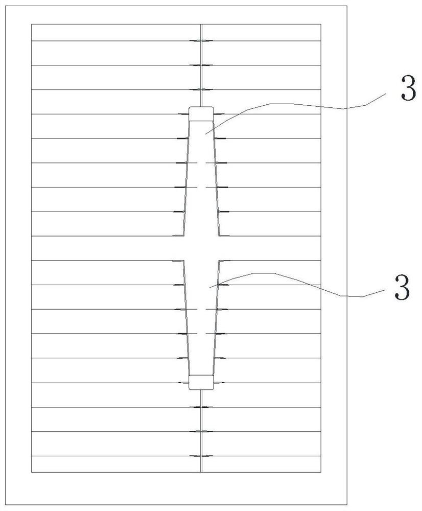
[0036] Such as Figure 1-3 As shown, the battery screen in the prior art is divided into several interconnected units 1, each of which is provided with a harpoon-type welding area 3 at both ends of the main grid line 2 on each unit 1, in addition, Near the cell cutting line OC, there are two mirror-symmetrical spear-shaped pads 3 , and when cutting in half, there is a spear-shaped pad 3 at both ends of the busbar 2 of each half.

[0037] The spear-type welding area 3 plays the role of collecting current and eliminating the difference of sight, but on the other hand, the spear-type welding area 3 also increases the shading area and reduces the battery efficiency.

[0038] The front graphic structure of the solar cell provided by this embodiment, such as Figure 4 As shown, the entire battery screen includes several units 1 isolated from each other by dividing lines OC, and several main grid lines 2 are arranged on the front of the unit 1, and the main grid lines on different u...

Embodiment 2

[0043] This embodiment provides a solar cell adopting the above-mentioned front pattern structure. Several busbars 2 are provided on the front of the unit 1 , each busbar 2 on each unit 1 is provided with a harpoon pad 3 at only one end, and the harpoon pad 3 is located on the front of the unit 1 .

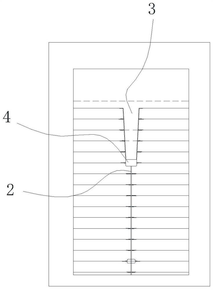
[0044] Such as figure 2 As shown, the size of the pad 4 of a solar cell will be different, and the size of the connecting harpoon pad 3 is relatively large. The increase of the pad will lead to an increase in the amount of silver paste, an increase in cost, and an increase in the volume of the cell. , the shading area increases, reducing battery efficiency.

[0045] In this embodiment, the ends of the busbars are connected to the spear-shaped pads 3 through pads 4 , and the pads 4 are in the shape of a cross. Several pads 4 are evenly spaced on the busbar 2 and between the two pads 4 connected to the spear-shaped pads 3 .

[0046]The existing pad body is rectangular, and after...

Embodiment 3

[0059] This embodiment provides a photovoltaic module formed by adopting the above-mentioned solar cells, which are connected in series and / or in parallel, and subjected to processes such as encapsulation.


PUM

PropertyMeasurementUnit
lengthaaaaaaaaaa
lengthaaaaaaaaaa
lengthaaaaaaaaaa

Abstract

The invention provides a front pattern structure of a solar cell, and belongs to the technical field of solar cells. The front pattern structure comprises a plurality of units (1), a plurality of maingrid lines (2) are arranged on the front surface of each unit (1), and the main grid lines on different units (1) are not connected, and a harpoon type welding area (3) is arranged at only one end ofthe main grid line (2) on each unit (1), and the harpoon type welding area (3) is located at the front surface of the units. The invention further discloses a solar cell adopting the front graphic structure and a photovoltaic module of the solar cell. Compared with the traditional mode that the two ends of each main grid line are provided with the harpoon type welding areas, the front graph structure has the advantages that the harpoon-type welding area at one end is omitted, the shading area is reduced, the silver paste consumption is reduced, and the battery efficiency and the assembly power are improved.

Description

technical field [0001] The invention belongs to the technical field of units, and in particular relates to a front pattern structure of a solar cell, a solar cell and a photovoltaic module thereof, which can effectively reduce the shading area and reduce the consumption of silver paste. Background technique [0002] At present, the photovoltaic industry has gradually adopted a multi-busbar cell structure. The width of the busbar on the front of the battery is small, usually <100um. The busbar is a long strip that runs through the pads. As a result of the flow process and lamination process after welding, the end of the main grid is stressed, resulting in fragments. In addition, the solder ribbon used to connect the battery on the component end is a circular solder ribbon, usually with a diameter of about 300um. Therefore, in the actual welding process, the welding effect will be poor and the circular solder ribbon will be offset. [0003] In order to solve the above prob...

Claims


Application Information

Patent Timeline
Patent Type & Authority Applications(China)
IPC IPC(8): H01L31/0224H01L31/042
CPCH01L31/022433H01L31/042Y02E10/50
Inventor 徐建美高纪凡张学玲
Owner TRINA SOLAR CO LTD
Why Eureka
Try Eureka