Method for printing pattern on solar battery sheet

A technology for printing solar cells and patterns, applied in printing, circuits, printing devices, etc., can solve problems such as the negative impact on the electrical performance of solar cells, and achieve the effect of not affecting current transmission and not increasing the shading area

Inactive Publication Date: 2011-09-14
JETION SOLAR HLDG
View PDF7 Cites 12 Cited by
  • Summary
  • Abstract
  • Description
  • Claims
  • Application Information

AI Technical Summary

Problems solved by technology

[0004] In some cases, in order to reflect the identity of the manufacturer on the battery sheet, the battery manufacturer needs to set a logo on the battery sheet. However, if the location of the label is not selected properly, it will have a negative impact on the electrical performance of the battery sheet.

Method used


Image

  • Method for printing pattern on solar battery sheet
  • Method for printing pattern on solar battery sheet
  • Method for printing pattern on solar battery sheet

Examples


Embodiment 1

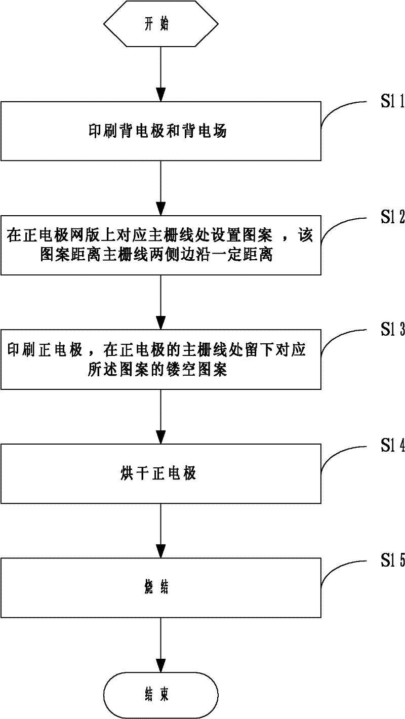
[0038] This embodiment provides a method for printing patterns on solar cell sheets, the basic process is as follows figure 1 shown, including the following steps:

[0039] Step S11 , printing the back electrode and the back electric field.

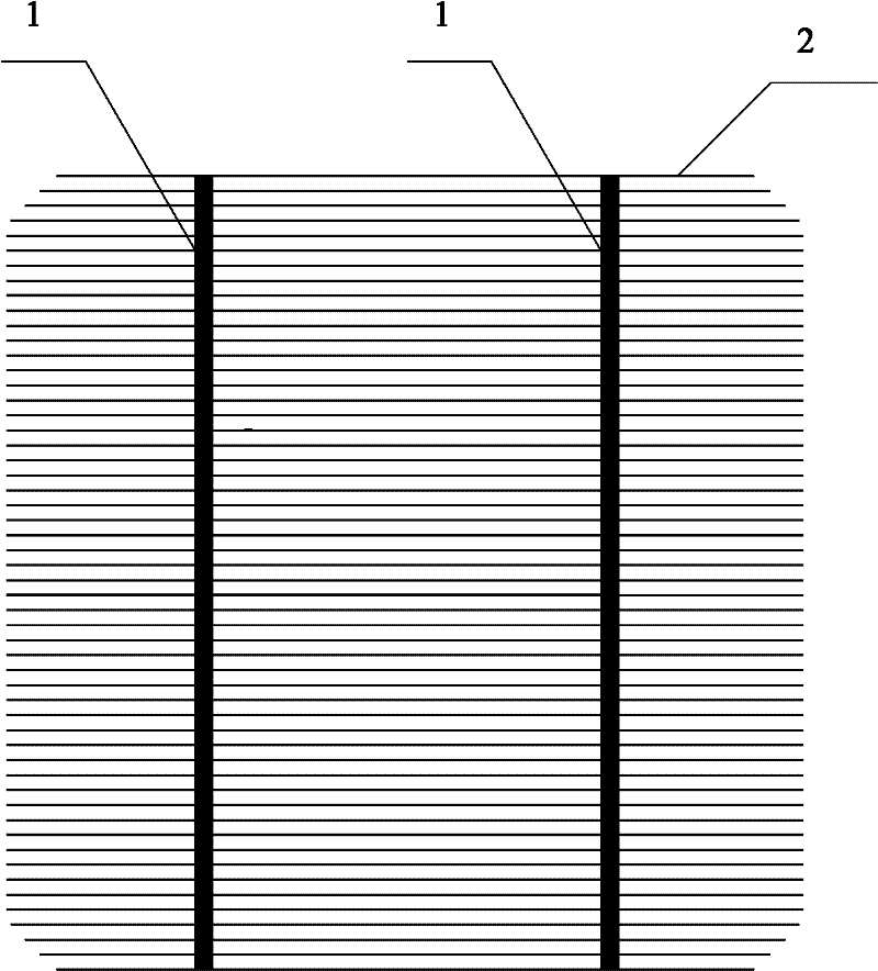
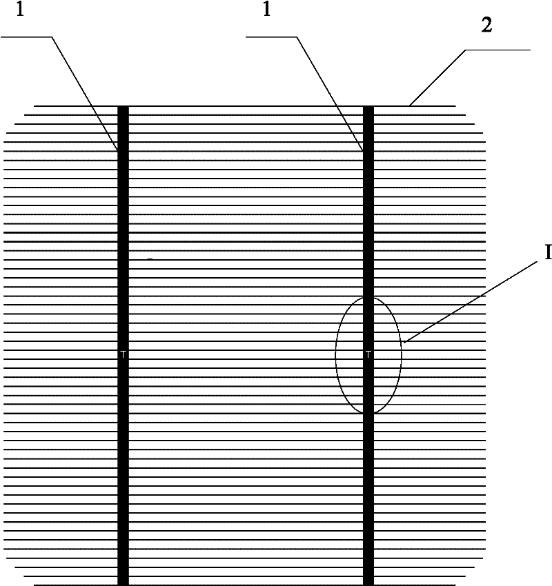
[0040] Step S12 , setting a pattern on the positive electrode screen corresponding to the busbar, and the pattern is a certain distance away from the edges on both sides of the busbar.

[0041] Step S13 , printing the positive electrode, leaving a hollow pattern corresponding to the pattern at the busbar of the positive electrode.

[0042] Step S14, drying the positive electrode.

[0043] Step S15, sintering.

[0044] The embodiment of the present invention chooses to set the pattern on the busbar, as long as the pattern does not cut off the busbar, it will not affect the electrical performance of the solar cell, and realizes the effect of setting the logo on the solar cell.

[0045] A specific example is used to supplement the descri...

Embodiment 2

[0061] This embodiment provides yet another method for printing patterns on solar cell sheets, the basic process of which is as follows Figure 5 shown, including the following steps:

[0062] Step S501, printing the back electrode and the back electric field;

[0063] Step S502, printing the positive electrode and drying;

[0064] Step S503, sintering;

[0065] Step S504, setting a pattern on the main grid line of the positive electrode.

[0066] The present embodiment is the same as the first embodiment in that the patterns are arranged on the busbars, and the difference is that the patterns are arranged after the printing and sintering is completed. In comparison, the examples save more slurry.

[0067] The specific method of setting the pattern on the busbar of the positive electrode may be: printing the pattern with a preset paste on the busbar of the positive electrode, or directly using a tool to print the pattern on the busbar of the positive electrode Draw patterns...


PUM


Abstract

The embodiment of the invention discloses a method for printing a pattern on a solar battery sheet, comprising the steps of: printing a back electrode and a back electric field; arranging a pattern at a place corresponding to a main grid line on a positive electrode screen, wherein the pattern is spaced from two side edges of the main grid line at a certain distance; printing a positive electrode and printing a hollow pattern corresponding to the pattern at the main grid line of the positive electrode; drying the positive electrode; and carrying out sintering. Another method disclosed by the embodiment of the invention comprises the steps of: printing a back electrode and a back electric field; printing a positive electrode and drying the positive electrode; carrying out sintering; and arranging a pattern on a main grid line of the positive electrode. The target of the pattern arrangement is the main grid line and the electric property of the solar battery sheet is not influenced if the main grid line is not cut off by the pattern, so that the aim of arranging a mark on the solar battery sheet is realized under the conditions of not increasing the shading area and not influencing the current transmission.

Description

technical field [0001] The invention relates to the technical field of solar energy manufacturing, and more specifically, relates to a method for printing patterns on solar cells. Background technique [0002] A solar cell, also known as a photovoltaic cell, is a semiconductor device that converts the sun's light energy directly into electrical energy. Because it is a green product, does not cause environmental pollution, and is a renewable resource, solar cells are a new energy source with broad development prospects in today's energy shortage situation. [0003] The manufacturing process of solar cells generally has the following steps: chemical cleaning and surface texture treatment, diffusion junction, peripheral etching, deposition of anti-reflection film, printing electrodes, and sintering. In the process of converting light energy into electrical energy in a solar cell, the photogenerated carriers generated inside need to be collected and extracted through external p...

Claims


Application Information

Patent Timeline
Patent Type & Authority Applications(China)
IPC IPC(8): B41M1/12B41M1/26H01L31/18
CPCY02P70/50
Inventor 孙林李扬王守志祝耀华于海娇
Owner JETION SOLAR HLDG
Why Eureka
Try Eureka