An antenna pointing adjustment mechanism
A technology for adjusting the mechanism and the direction of the antenna, which is applied to the direction of the antenna, electrical components, etc. to achieve the effect of simplifying the feeding system
Active Publication Date: 2013-04-17
XIAN INSTITUE OF SPACE RADIO TECH
View PDF0 Cites 8 Cited by
- Summary
- Abstract
- Description
- Claims
- Application Information
AI Technical Summary
Problems solved by technology
This kind of structure is feasible for the focus-fed antenna, but it is not feasible for the double-biased Gregorian antenna of the nulling antenna because the rotation mechanism placed near the focus will block the primary beam of the antenna.
Method used
View moreImage
Smart ImageViewing Examples
Examples
Embodiment Construction
Login to View More PUM
 Abstract
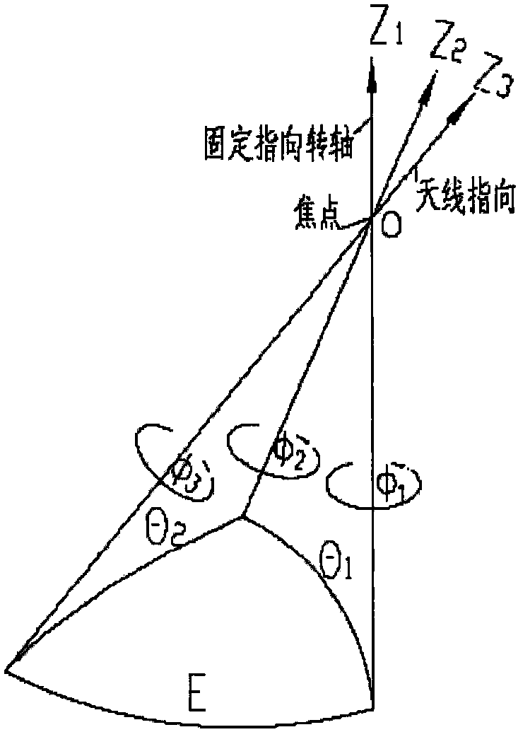
The invention discloses an antenna pointing adjustment mechanism. The adjustment mechanism includes three rotating units. Every two rotating units are connected by an angle bracket and a round bracket to form a three-axis pointing mechanism. The three rotation axes intersect at the focus of the reflector. , where the second rotation unit rotates around the first rotation unit to generate the required azimuth angle, the third rotation unit rotates around the second rotation unit to generate the elevation angle, and the third rotation unit can adjust the polarization direction of the antenna, so The adjustment of the antenna beam can be realized by controlling these two rotation angles. The mechanism can be placed far away from the focal point, will not block the primary beam of the antenna and can avoid the feed array and waveguide feeder, simplify the feeding system, make the feed source fixed at the focal point, the reflector rotates around the focal point, and allow The reflector can be rotated over a wide range without affecting the electrical performance of the antenna; this advantage is even more pronounced for bias-fed antennas.
Description
technical field The invention relates to an antenna pointing adjustment mechanism, in particular to a three-axis antenna pointing mechanism capable of rotating around a focal point without blocking the primary beam of the antenna. Background technique There are generally two ways to change the antenna beam pointing. One way is to change the overall pointing of the antenna; the other way is to fix the feed source at the focal point and rotate the reflector around the focal point. The method of changing the overall beam pointing of the antenna has a large rotation range, but requires the radio frequency signal to pass through the microwave rotary joint and a more complicated feeder, which not only increases the feeder loss and standing wave ratio, but also complicates the feeder system. For some satellite antennas, since they have a feed array composed of multiple feed sources, multiple rotating joints are required, so that too many feed paths cannot be realized structurally. ...
Claims
Login to View More Application Information
Patent Timeline
 Patent Type & Authority Patents(China)
IPC IPC(8): H01Q3/02
Inventor 冯小星宋剑鸣
Owner XIAN INSTITUE OF SPACE RADIO TECH
Features
- R&D
- Intellectual Property
- Life Sciences
- Materials
- Tech Scout
- Unparalleled Data Quality
- Higher Quality Content
- 60% Fewer Hallucinations
Learn More Browse by: Latest US Patents, China's latest patents, Technical Efficacy Thesaurus, Application Domain, Technology Topic, Popular Technical Reports.
© 2025 PatSnap. All rights reserved.Legal|Privacy policy|Modern Slavery Act Transparency Statement|Sitemap|About US| Contact US: help@patsnap.com


