
Laser generating system and method

A laser and laser technology, applied in the laser field, can solve problems such as poor pulse stability, large pulse laser width, and non-adjustable pulse waveform

Active Publication Date: 2015-08-26
TSINGHUA UNIV
View PDF7 Cites 7 Cited by
  • Summary
  • Abstract
  • Description
  • Claims
  • Application Information

AI Technical Summary

Problems solved by technology

[0009] The technical problem to be solved by the present invention is: the pulse laser width is large, the pulse stability is poor and the pulse waveform cannot be adjusted under the high repetition rate in the prior art

Method used


Image

  • Laser generating system and method
  • Laser generating system and method

Examples


Embodiment Construction

[0033] Embodiments of the present invention will be described in detail below with reference to the accompanying drawings.

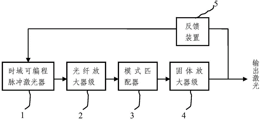
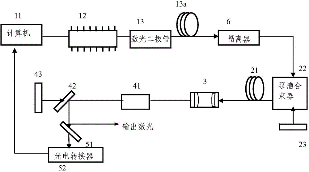
[0034] figure 1 A schematic structural diagram of a laser generating system according to an embodiment of the present invention is shown. like figure 1 As shown, the laser generating system includes: a time-domain programmable pulse laser 1 , a fiber amplifier stage 2 , a mode matcher 3 , a solid-state amplifier stage 4 and a feedback device 5 . A time-domain programmable pulse laser 1 , a fiber amplifier stage 2 , a mode matcher 3 and a solid amplifier stage 4 are arranged in sequence, and the feedback device 5 is connected between the time-domain programmable pulse laser 1 and the solid amplifier stage 4 .

[0035] A time-domain programmable pulse laser 1 is used to generate an initial pulse laser with a preset time-domain waveform.

[0036] The fiber amplifier stage 2 is used to amplify the power of the initial pulse laser generated by the time-dom...


PUM


Abstract

The invention relates to a laser generating system and method. The system includes a time domain programmable pulse laser, a fiber amplifier stage, a pattern matcher, a solid state amplifier stage and a feedback device; the time domain programmable pulse laser generates initial pulse laser with preset time domain waveform; the fiber amplifier stage performs power amplification on the initial pulse laser; the amplified laser and pump light in the solid state amplifier stage are subjected to pattern matching through the pattern matcher; the solid state amplifier stage performs power amplification on the laser which has been processed by the pattern matcher; the feedback device obtains feedback signals and transmits the feedback signals to the time domain programmable pulse laser; and the time domain programmable pulse laser adjusts the time domain waveform of the initial pulse laser according to the feedback signals, so that the solid state amplifier stage can output laser with preset time domain waveform. With the laser generating system and method of the invention adopted, high-repetition rate and high-brightness laser with preset time domain waveform can be generated.

Description

technical field [0001] The invention relates to the field of lasers, in particular to a laser generating system and method. Background technique [0002] Beam quality is a measure of the directional transmission capability of the laser or the energy concentration of the focused focal spot, and is an important technical performance indicator of the laser. The International Standardization Committee announced the beam quality evaluation standard in 1991, that is, the beam quality factor M 2 Evaluate the beam. The laser is used as a light source, and the brightness is a very important parameter, which is proportional to the laser power and is related to the beam quality factor M 2 Inversely proportional to the square of . [0003] Q-switching technology is generally used to obtain high peak power pulsed laser output, and the inherent characteristics of Q-switched lasers are that as the repetition frequency increases, the pulse width also increases, and the pulse stability de...

Claims


Application Information

Patent Timeline
IPC IPC(8): H01S3/10
Inventor 柳强聂明明陆富源巩马理
Owner TSINGHUA UNIV
Learn More