
Outward rotation permanent magnet brushless motor

A permanent magnet brushless motor, external rotation technology, applied in the direction of electrical components, electromechanical devices, electric components, etc., can solve the problems of poor support frame design, low service life of parts, wear and tear, etc., to solve the problem of poor structural rigidity , Reduce bearing clearance, improve the effect of improper bearing force

Active Publication Date: 2017-07-14
ATECH TOTALSOLUTION
View PDF8 Cites 1 Cited by
  • Summary
  • Abstract
  • Description
  • Claims
  • Application Information

AI Technical Summary

Problems solved by technology

[0004] As mentioned above, due to the poor design of the support frame of the existing fitness equipment, there are gaps between the components and the axial stress cannot be directly and continuously transmitted, resulting in poor rigidity of the overall structure, low service life of parts and energy consumption. Therefore, in order to solve the above-mentioned problems, the main purpose of the present invention is to provide an externally rotating permanent magnet brushless motor, which is an externally rotating permanent magnet brushless motor with high rigidity transmission and support structure, which mainly makes the Each component is a non-axial clearance transmission structure adjacent to each other, and the axial preload mechanism reduces the bearing clearance to improve the rigidity of the transmission structure. The joints between the other two support frames are distributed around the support frame. And more than one of the connecting parts is above the central point of the transmission shaft, which can reduce the deformation of the support frame and improve the life of the parts, and solve the problems of poor structural rigidity, low service life of parts and energy consumption of existing fitness equipment

Method used


Image

  • Outward rotation permanent magnet brushless motor
  • Outward rotation permanent magnet brushless motor
  • Outward rotation permanent magnet brushless motor

Examples


Embodiment Construction

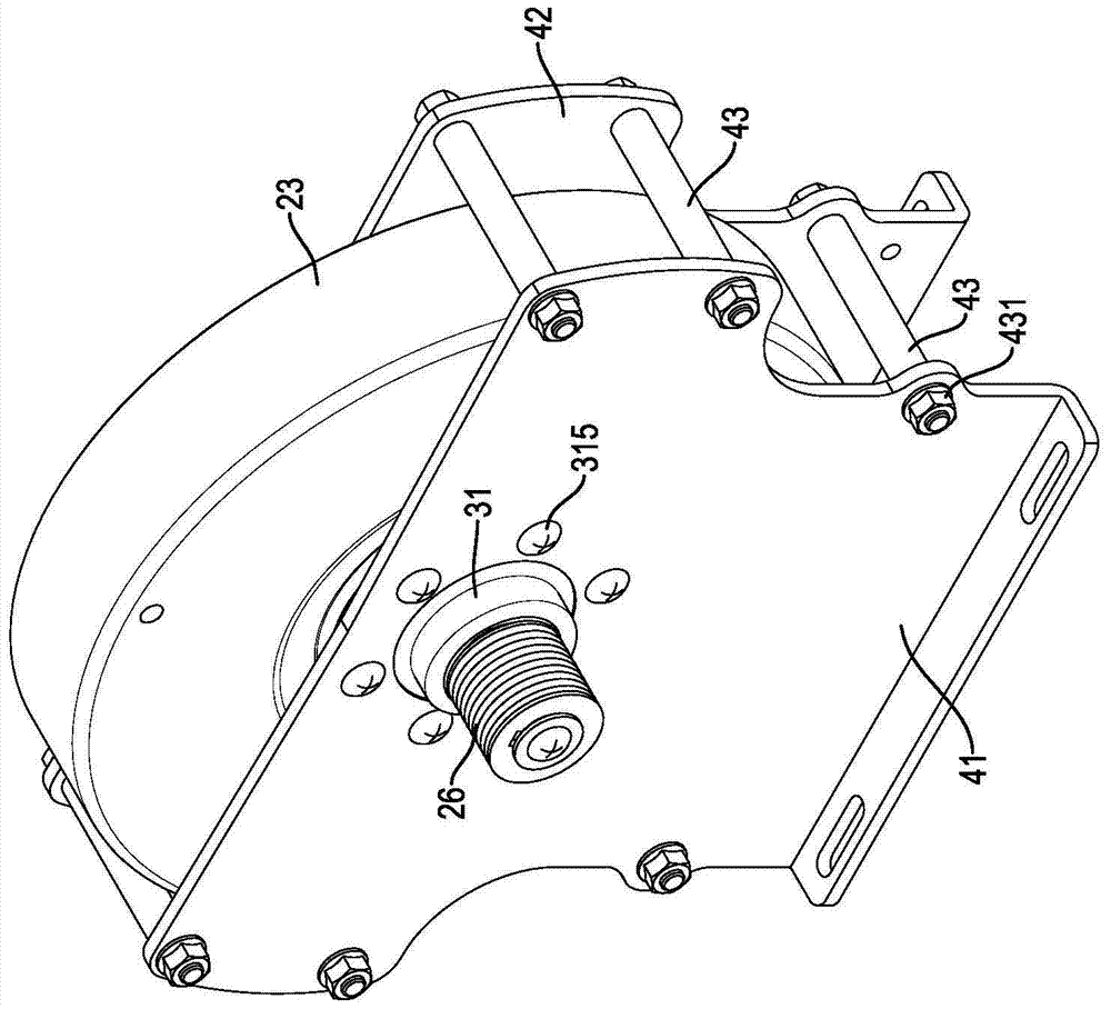
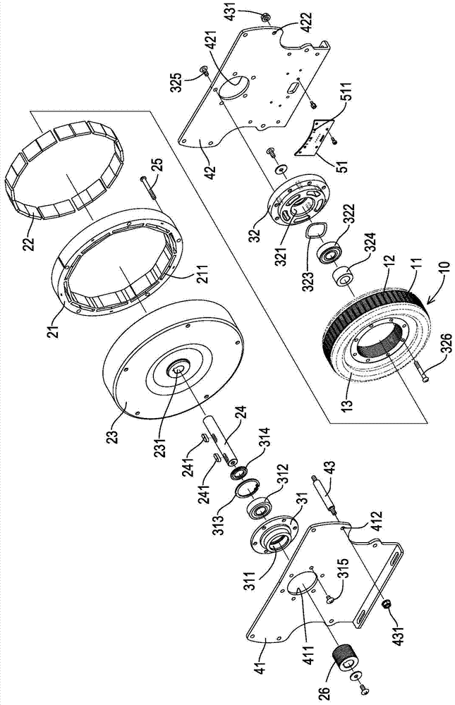
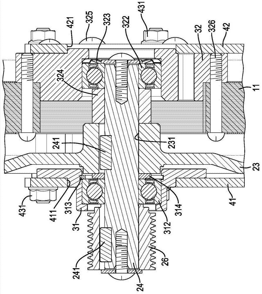
[0062] For a preferred embodiment of the present invention, please refer to Figures 1 to 3 Shown, be to be provided with a rotatable rotor 21 on the outer ring of a certain stator 10 periphery, be provided with a plurality of permanent magnets 22 in this rotor 21, and be fixedly provided with a flywheel 23 on the outside of rotor 21 periphery, this flywheel 23 and stator A front support frame 41 and a rear support frame 42 are respectively provided on the opposite two outer sides of the stator 10. The stator 10 is connected to the rear support frame 42. The end of the front support frame 41 opposite to the flywheel 23 is provided with a front bearing seat 31. The end of the rear supporting frame 42 opposite to the stator 10 is provided with a rear bearing seat 32 , and a drive shaft 24 is penetrated between the front bearing seat 31 and the rear bearing seat 32 , and the drive shaft 24 is connected to the flywheel 23 .

[0063] The stator 10 is mainly composed of a plurality ...


PUM


Abstract

The invention relates to an externally rotating permanent magnet brushless motor. A flywheel, a rotor and a stator are arranged between a front support frame and a rear support frame. The front and rear support frames are respectively provided with a bearing seat and two The bearing housings are respectively equipped with a bearing and more than one washer, and a transmission shaft is passed through it. One of the bearing housings is equipped with a wave spring. Each component is a non-axial clearance transmission structure and a preloading mechanism that are adjacent to each other. When the transmission shaft is pulled by the lateral force, it is not easy to deform and can improve the rigidity of the bearing group body. In addition, there are multiple joints between the front and rear support frames to maintain the equiaxial relative joint. More than one joint is designed Above the central point of the transmission shaft, the rigidity of the supporting mechanical structure is strengthened, and the problems of poor structural rigidity and low service life of the existing fitness equipment are solved.

Description

technical field [0001] The invention relates to an externally rotating permanent magnet brushless motor. Background technique [0002] Existing belt-driven fitness equipment, such as an exercise bike, is driven by the user's pedals to drive the flywheel of the exercise bike, and the hybrid brake device makes the flywheel generate resistance when rotating, thus allowing the user to step on the exercise bike. It can consume heat when the hybrid braking device is used, because the braking torque generated by the generator of the hybrid braking device can only provide partial braking force, and the main braking force still requires an additional hysteresis braking device, so please refer to Figure 13 and 14 , is the U.S. invention patent No. 6084325 "Brake device with a combination of power-generating and eddy-current magnetic resistance (combination of power-generating and eddy-current magnetic resistance braking device)", which is between two support frames 81 with a The tra...

Claims


Application Information

Patent Timeline
Patent Type & Authority Patents(China)
IPC IPC(8): H02K29/00H02K7/02H02K7/18H02K5/16H02K1/27
CPCY02E60/16
Inventor 罗应照袁绍中苏奕丞洪士伟
Owner ATECH TOTALSOLUTION
Learn More