
Bevel gear drive device

A technology of bevel gear transmission and bevel gear, which is applied in the direction of gear transmission, transmission, transmission parts, etc., can solve the problems of bevel gear tooth surface contact fatigue, noise, and influence on transmission stability, so as to achieve less fatigue and lower noise , the effect of smooth transmission

Inactive Publication Date: 2015-08-26
蒋继章
View PDF3 Cites 1 Cited by
  • Summary
  • Abstract
  • Description
  • Claims
  • Application Information

AI Technical Summary

Problems solved by technology

[0003] There are following deficiencies in the prior art: since the fulcrum bearings of the power output shaft and the power input shaft are on the other side of the two shafts, when the bevel gear transmission works, especially when the load is constantly changing, the power output The shaft and the power input shaft are prone to elastic deformation, which affects the smooth transmission, deteriorates the meshing, and is prone to a series of problems such as bevel gear tooth surface contact fatigue, wear, and noise, which need to be improved
[0004] It should be said that the above-mentioned bevel gear transmission structure is one of the most basic, common and oldest structures in the mechanical field.

Method used


Image

  • Bevel gear drive device

Examples


Embodiment Construction

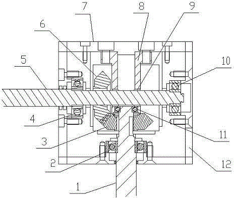
[0020] Referring to accompanying drawing 1, the first embodiment of the present invention is a bevel gear transmission in which the power output shaft is perpendicular to the power input shaft, which includes a square frame composed of four frames 12, a power input shaft 1, a bearing 2. Drive bevel gear 3, bushing 8, middle support bearing 11, power output shaft 5, driven bevel gear 6, bearing 4, bearing 10 installed on power output shaft 5 installed on power input shaft 1. Sleeve 8 is a metal rigid rotary part, the central axis of sleeve 8 and the central axis of power input shaft 1 are on the same straight line, and there is a through hole 9 with a diameter larger than the outer diameter of power output shaft 5 on the sleeve 8. One end of the casing 8 is fixedly installed on the support seat 7 on the frame, and the other end of the casing 8 is installed with a middle support bearing 11, the outer ring of the middle support bearing 11 is fixedly connected with the inner wall o...


PUM


Abstract

The invention relates to a bevel gear drive device. The bevel gear drive device comprises a power input shaft, a power output shaft, a driving bevel gear and a driven bevel gear, and further comprises a rigid rotation piece which is coaxial with the power input shaft. A through hole with the diameter larger than that of the power output shaft is formed in the rotation piece. One end of the rotation piece is fixedly arranged on a supporting base, and a middle supporting bearing is arranged at the other end of the rotation piece. One end of the power input shaft is connected with the other end of the rotation piece through the middle supporting bearing, and the other end of the power input shaft is arranged on an external supporting base through a bearing. The external supporting base is located on the opposite side of the fixed end of the rotation piece. The power output shaft penetrates through the through hole in the rotation piece, and the two ends of the power output shaft are arranged on the corresponding supporting bases through bearings respectively. The driving bevel gear is meshed with the driven bevel gear. The bevel gear drive device has the advantages that each shaft in the bevel gear drive device is not prone to elastic deformation; the bevel gears are well meshed; drive is stable; the tooth surfaces of the bevel gears are not prone to fatigue or abrasion, and noise is obviously reduced.

Description

technical field [0001] The invention relates to the technical field of mechanical transmission, in particular to a bevel gear transmission. Background technique [0002] Bevel gear transmission is one of the common transmission structures in mechanical transmission, and is generally used for power or speed transmission between two intersecting axes in space. Among them, bevel gears are divided into straight bevel gears, spiral bevel gears, zero-degree bevel gears, hypoid gears, helical bevel gears, etc. The commonly used bevel gear transmission consists of two bevel gears installed on the top of two shafts respectively. , among the two shafts, one is the power output shaft and the other is the power input shaft, and the intersection angle between the two shafts is 90 0 , the two bevel gears mesh. When working, the rotation of the power output shaft drives the bevel gear mounted on the shaft, that is, the driving bevel gear, which meshes with the driven bevel gear installed...

Claims


Application Information

Patent Timeline
Patent Type & Authority Applications(China)
IPC IPC(8): F16H57/023F16H57/021F16H1/14
CPCF16H57/023F16H1/14F16H57/021
Inventor 蒋剑蒋继章
Owner 蒋继章
Learn More