Micro motor magnetic steel assembly device

A technology for micro-motors and assembly equipment, which is applied in electromechanical devices, manufacturing motor generators, circuits, etc., can solve problems such as increased labor intensity, enterprise losses, and impact on enterprise production, and achieves reduced labor intensity, reduced production costs, and stabilized The effect of the staff

Active Publication Date: 2014-06-18
广安市超颖电子科技有限公司
View PDF5 Cites 10 Cited by
  • Summary
  • Abstract
  • Description
  • Claims
  • Application Information

AI Technical Summary

Problems solved by technology

[0003] 1. The magnetization and installation process of the magnetic steel requires a lot of labor and time, and the production efficiency is extremely low;
[0004] 2. In the process of manually clamping the magnet with tweezers, it is extremely easy for the tweezers to damage the magnet and the brush. During the installation process, it is also easy to cause the magnet to not be placed flat and cause a bad motor, which leads to the scrapping of materials. Enterprises bring losses and increase production costs;
[0005] 3. Because workers stare at such a small magnetic steel for a long time, it will cause visual fatigue and increase labor intensity. It is difficult for workers to adapt, which makes the staff flow frequently and difficult to stabilize, which seriously affects the production of enterprises.

Method used


Image

  • Micro motor magnetic steel assembly device
  • Micro motor magnetic steel assembly device
  • Micro motor magnetic steel assembly device

Examples


Embodiment Construction

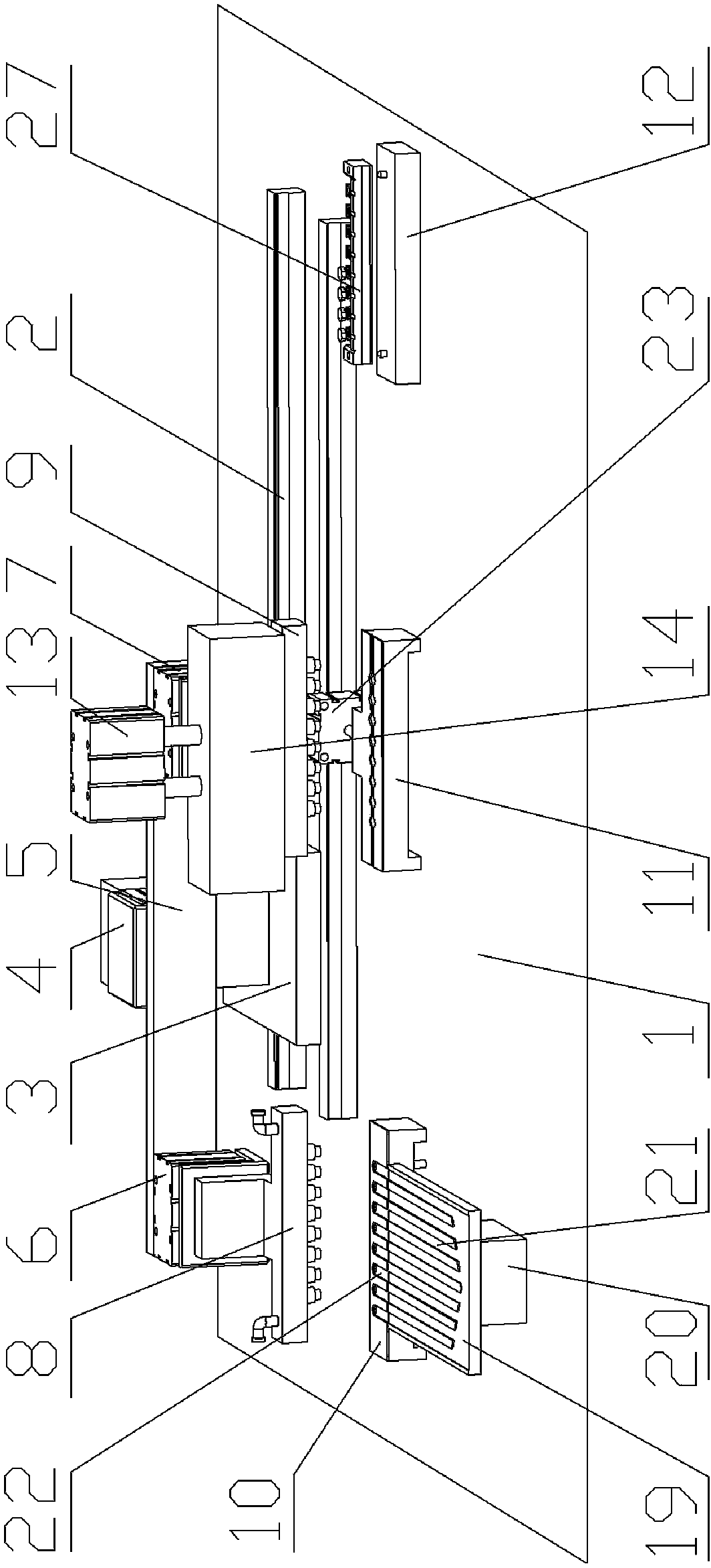
[0035] see Figure 1 to Figure 7 , is an embodiment of the assembly equipment of micro-motor magnetic steel, including a working platform 1, the working platform is fixed on a frame, and the working platform 1 is provided with two guide rails 2 parallel to each other, and the two guide rails are fixed on the working platform by bolts. On the platform 1, a mobile supporting seat 3 is provided on the two guide rails 2, and a driving device is connected with the mobile supporting seat 3 to drive the mobile supporting seat to translate along the two guide rails. Further, the lower part of the mobile supporting seat 3 extends to the guide rails 2, the extension part of the mobile supporting base 3 is screwed with a screw rod, the screw rod is parallel to the two guide rails 2, and one end of the screw rod is connected with the driving motor to form a drive for driving the moving supporting base 3 to translate along the two guide rails 2. device.

[0036] Described mobile supportin...


PUM

PropertyMeasurementUnit
diameteraaaaaaaaaa
diameteraaaaaaaaaa

Abstract

The invention discloses a micro motor magnetic steel assembly device which comprises a working platform and two guide rails on the working platform. A movable supporting base is arranged on the two guide rails. A third air cylinder is arranged on the movable supporting base. An installation arm parallel to the two guide rails is fixed to a piston rod of the third air cylinder. The two ends of the installation arm are provided with a first air cylinder and a second air cylinder. A first magnetic steel attraction device is arranged on a piston rod of the first air cylinder. A second magnetic steel attraction device is arranged on a piston rod of the second air cylinder. A first magnetic steel positioning base, a second magnetic steel positioning base and a shell positioning base are sequentially arranged on the working platform along the straight line. The distance between every two adjacent positioning bases is equal to the distance between the first magnetic steel attraction device and the second magnetic steel attraction device. A fourth air cylinder is installed on the working platform through a support. A piston rod of the fourth air cylinder extends downwards. A magnetizing apparatus corresponding to the second magnetic steel positioning base is arranged on the piston rod of the fourth air cylinder. According to the micro motor magnetic steel assembly device, the labor intensity of workers is reduced, and production efficiency is improved.

Description

technical field [0001] The invention relates to the field of micro-motors, in particular to an assembly equipment for magnets of micro-motors. Background technique [0002] see figure 1 It is a structural schematic diagram of an existing micro-motor magnet. This magnet 30 is annular, and fan-shaped north and south magnetic regions are distributed on the annular magnet; see figure 2 It is a schematic structural diagram of a housing 31 with a brush 32 installed on an existing micro motor, and the magnetic steel needs to be covered and installed above the brush. The magnetic steel and casing of the micro motor are very small, the diameter of the casing is as low as 9.80mm, and the diameter of the magnetic steel is as low as 8.50mm. At the same time, the small magnets and brushes are easily deformed, resulting in power supply and rotation failures of the micro motor. For a long time, in the magnetization of micro motor magnets and the installation of magnets, the procedures ...

Claims


Application Information

Patent Timeline
Patent Type & Authority Applications(China)
IPC IPC(8): H02K15/00H01F13/00
Inventor 邓自军
Owner 广安市超颖电子科技有限公司
Why Eureka
Try Eureka