Ultrasonic flaw detection auxiliary device and operating method thereof

A technology of auxiliary device and operation method, which is applied to measurement devices, material analysis using sonic/ultrasonic/infrasonic waves, instruments, etc., can solve problems such as low work efficiency, influence on flaw detection efficiency, and large influence of human factors, so as to improve work efficiency , Guarantee the quality of detection and ensure the effect of stability

Inactive Publication Date: 2010-04-14
CHINA FIRST HEAVY IND +1
View PDF0 Cites 10 Cited by
  • Summary
  • Abstract
  • Description
  • Claims
  • Application Information

AI Technical Summary

Problems solved by technology

[0003] 1. The optimal thickness of the coupling layer is difficult to control
Because the thickness is adjusted directly by the pressure of the human hand holding the probe, human factors have a greater influence
[0004] 2. The work efficiency is low, and the operator is prone to fatigue
In the manual flaw detection of steel plates, flaw detectors must squat on the steel plate to scan. If the inspection takes a long time, the waist and arms of the flaw detectors will be easily fatigued, which will affect the efficiency of flaw detection.
[0005] 3. Due to the influence of human factors, the coverage rate of each scan of the probe is not easy to control, and it is easy to cause missed detection

Method used


Image

  • Ultrasonic flaw detection auxiliary device and operating method thereof
  • Ultrasonic flaw detection auxiliary device and operating method thereof
  • Ultrasonic flaw detection auxiliary device and operating method thereof

Examples


Embodiment Construction

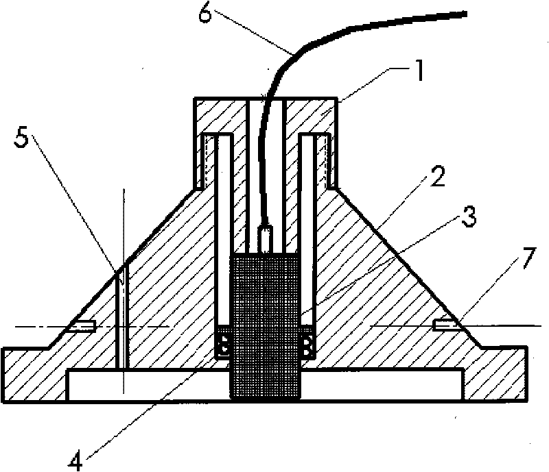
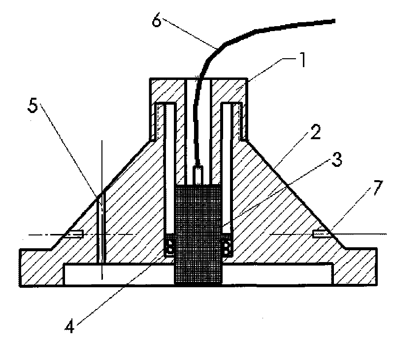
[0026] The present invention will be further described below in conjunction with the accompanying drawings. Such as Figure 1-2 As shown, an auxiliary device for ultrasonic flaw detection includes a housing 2, a gland 1 and a spring 4. The housing 2 is conical and has a circular hole in the center for placing the probe 3. The spring 4 is located at the bottom of the circular hole. On the platform, the gland 1 is installed on the upper part of the casing 2 by threaded connection, and the casing 2 is provided with a water injection hole 5 , and the diameter and height of the circular hole are determined according to the size of the probe 3 .

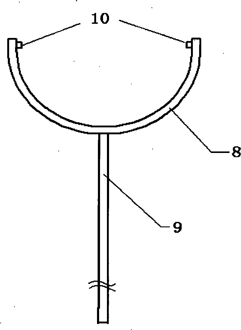
[0027] The casing 2 of the present invention is also connected with an extension rod 9 , and the clip 8 at one end of the extension rod 9 is installed in the pin hole 7 on the casing 2 through the pin shaft 10 .

[0028] An operation method of an ultrasonic flaw detection auxiliary device includes the following steps: put the probe 3 conn...


PUM


Abstract

The invention discloses an ultrasonic flaw detection auxiliary device and an operating method thereof. The device comprises a shell, a clamping cap and a spring, wherein the shell is cone-shaped, and the center of the shell is provided with a round hole provided with a probe; the spring is positioned on a platform at the bottom of the round hole; and the clamping cap is arranged at the upper part of the shell in a way of threaded connection. The operating method comprises the following steps: arranging the probe connected with a cable inside the round hole of the shell and pressing the probe on the spring; and then, screwing the clamping cap, and adjusting the contact gap between the probe and the surface of a steel plate by the pressure of the pressured spring and the adjusting action of the clamping cap, so that the best thickness of a coupling layer required by detection can be reached. As the contact gap between the probe and the surface of the steel plate can be adjusted by the pressure of the pressured spring and the adjusting action of the clamping cap, the invention can control the best thickness of the coupling layer required by detection. The shell has heavier weight and larger size, so that the stability of the flaw detection auxiliary device can be ensured in the process of flaw detection scanning of the steel plate.

Description

technical field [0001] The invention relates to an ultrasonic detection device, in particular to an ultrasonic flaw detection auxiliary device and an operation method thereof. Background technique [0002] Ultrasonic flaw detection of steel plates is usually carried out by the manual probe contact method, and when there are special requirements, the angle probe contact method is also used for detection, but there are the following disadvantages: [0003] 1. The optimal thickness of the coupling layer is difficult to control. Because the thickness is adjusted directly by the pressure of the human hand holding the probe, human factors have a greater influence. [0004] 2. The work efficiency is low, and the operator is prone to fatigue. In the manual flaw detection of steel plate, the flaw detector must squat on the steel plate to scan. If the inspection takes a long time, the waist and arms of the flaw detector will be easily fatigued, which will affect the efficiency of fl...

Claims


Application Information

Patent Timeline
Patent Type & Authority Applications(China)
IPC IPC(8): G01N29/22
Inventor 张富生李信东
Owner CHINA FIRST HEAVY IND
Why Eureka
Try Eureka