Converter power cabinet

A power cabinet and converter technology, applied in the design field of the power cabinet cooling system, can solve the problems of partial discharge failure, reduced ventilation efficiency, reduced power density, etc., so as to improve device reliability, reduce device cost, and reduce fan pressure loss. small effect

Inactive Publication Date: 2015-08-26
ZHEJIANG HAIDE NEW ENERGY
View PDF4 Cites 11 Cited by
  • Summary
  • Abstract
  • Description
  • Claims
  • Application Information

AI Technical Summary

Problems solved by technology

[0004] First, the radiator uses air blowing to dissipate heat, and the uneven wind speed leads to low heat dissipation efficiency. At the same time, multiple power modules need to be equipped with fans, so the number of fans is increased, the cost is increased, and the fan volume is large, resulting in a decrease in power density;
[0005] Second, the IGBT radiator uses air suction to dissipate heat, which requires a large fan volume and volume, so it cannot be placed inside the power cabinet, but can only be placed outside the cabinet, increasing the peripheral volume of the power cabinet, resulting in unchanged installation;
[0006] Third, the cooling wind speed between the reactor wire packs is low, and the heat dissipation efficiency is low; Flying dust and particles block the air inlet, resulting in a decrease in ventilation efficiency and excessive temperature rise;
[0007] Fourth, the IP protection is low, which can easily lead to sand and dust entering the cavity of the power cabinet, deteriorating the environmental conditions of IGBTs and capacitors, leading to partial discharge and failure

Method used


Image

  • Converter power cabinet
  • Converter power cabinet
  • Converter power cabinet

Examples


Embodiment Construction

[0025] The following are specific embodiments of the present invention and in conjunction with the accompanying drawings, the technical solutions of the present invention are further described, but the present invention is not limited to these embodiments.

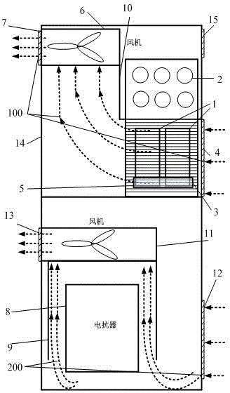
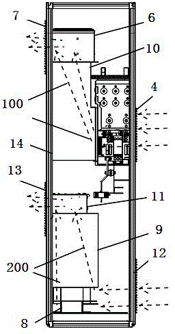
[0026] Such as figure 1 with figure 2 A power cabinet for a converter is shown, and the power cabinet is divided into two independent cooling air ducts, which are respectively a power module cooling air duct 100 and a reactor cooling air duct 200, and the power module cooling air duct It is surrounded by the first windshield 10 and the cabinet body 14, and the reactor cooling air duct 200 is surrounded by the second windshield 9 and the cabinet body 14, and the two air ducts are isolated from each other.

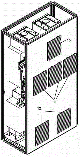
[0027] The reactor heat dissipation air duct 200 is provided with an air-cooled reactor 8 and a second fan 11, and the air-cooled reactor 8 is located below the second fan 11, and the third ventilation window 12 is loc...


PUM


Abstract

The invention discloses a converter power cabinet. A sealed cooling system comprises an IGBT power module, a fan, a reactor, an air damper and a cabinet body. the power cabinet is divided into an upper independent cooling air duct and a lower independent cooling air duct, the upper part is a power module cooling air duct 100, the lower part is a reactor cooling air duct 200, the two air ducts are isolated mutually, mutual influences are avoided, the air duct length can be reduced as two independent air ducts are divided, pressure losses of the fan are reduced, and the cooling efficiency is improved.

Description

technical field [0001] The invention relates to a converter power cabinet, in particular to the design of the cooling system of the power cabinet in the field of converters. Background technique [0002] With the rapid development of wind energy, wind power converters are required to be smaller in size and higher in power density, which requires taking away more losses per unit volume, thus requiring the design of a more efficient heat dissipation system. Therefore, the design of high-power heat dissipation system has become a key issue for wind power converter products. [0003] The wind power converter adopts the air-cooled heat dissipation method, which has two methods: blowing and suction. The blowing method directly dissipates heat to the heating device. The air duct design is simple and the cost is relatively low. The suction method dissipates heat evenly, and usually requires a centrifugal fan. The cost of fans is relatively high, but the number of fans is required t...

Claims


Application Information

Patent Timeline
Patent Type & Authority Applications(China)
IPC IPC(8): H02M1/00H05K7/20
CPCY02E10/76H02M1/00H05K7/20909
Inventor 吕怀明袁新荣季建强朱凯
Owner ZHEJIANG HAIDE NEW ENERGY
Why Eureka
Try Eureka