Supercharge Your Innovation With Domain-Expert AI Agents!

LED control circuit

A technology of LED controller and control circuit, which is applied in the direction of electric lamp circuit layout, electric light source, lighting device, etc. It can solve the problems of increasing production and application costs, increasing current flowing through LED, and reducing energy utilization rate for customers, and achieves consistency. Good, fewer peripheral devices, and the effect of improving utilization efficiency

Active Publication Date: 2015-08-26
SHANGHAI SHININGIC ELECTRONICS TECH CO LTD
View PDF4 Cites 1 Cited by
  • Summary
  • Abstract
  • Description
  • Claims
  • Application Information

AI Technical Summary

Problems solved by technology

[0008] However, Figure 4 The circuit shown is the same as figure 1 , figure 2 , image 3 The circuit shown is the same as most of the controller circuits in the current outdoor lighting market, and there are the following problems: On the one hand, in solar applications, the working range of the voltage required by customers is getting larger and larger, so that when the battery voltage is greater than the LED power supply voltage There will be a situation where the LED is directly connected, which will increase the current flowing through the LED, which will increase the power consumption and reduce the use time. In some circuits, a resistor is connected in series with the load LED in the peripheral circuit and a switch is added. Increase the cost of production and application; on the other hand, when the solar energy is charging, the LED lamp often encounters the situation of turning off and turning on and off, and a part of the leakage current flows through the LED, which leads to energy loss and reduces energy utilization.

Method used


Image

  • LED control circuit
  • LED control circuit
  • LED control circuit

Examples


Embodiment Construction

[0029] The present invention will be further described below in conjunction with the embodiments shown in the accompanying drawings.

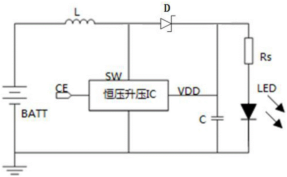
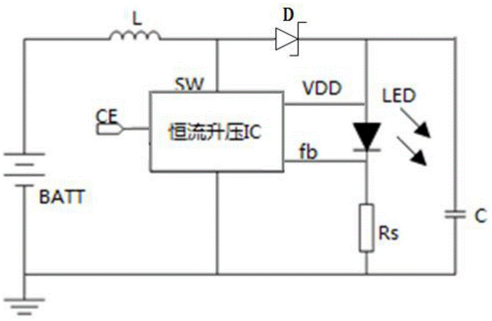
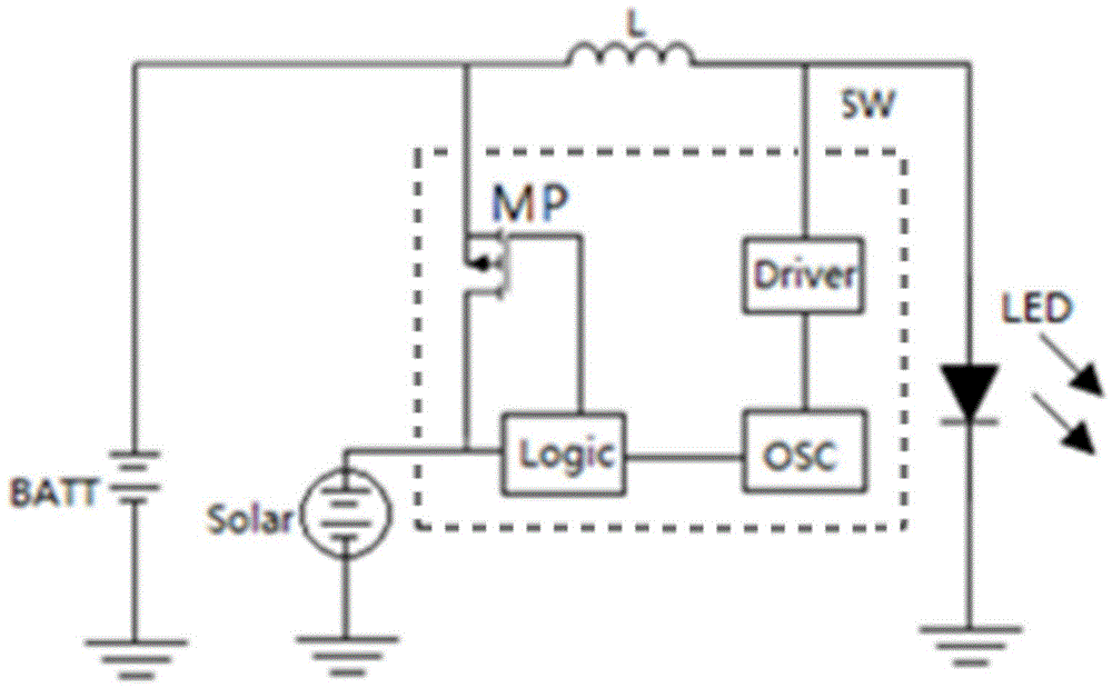
[0030] The present invention proposes an LED control circuit, which can effectively avoid the situation that the LED light is directly connected to the ground when the battery voltage is too high and the current is not controlled, can meet the current requirements required by different LED loads, and can effectively avoid When solar charging, the LED light turns off and keeps dimming, so it is especially suitable for solar applications. In this embodiment, the Figure 4 Based on the LED controller circuit shown in PFM mode, Figure 5 Shown is a schematic structural diagram of the LED control circuit in this embodiment. from Figure 5 As can be seen, the LED control circuit consists of Figure 4The LED controller circuit based on PFM mode shown, especially also includes such as Image 6 The effective LED shutdown circuit section shown.

[...


PUM


Abstract

The invention provides a LED control circuit. The circuit comprises a LED controller circuit, a constant voltage source, an inductor L and a turn-off circuit. A cathode of the constant voltage source is grounded and an anode is connected to one end of the inductor L. An internal switch pin of the LED controller circuit is connected to the other end of the inductor L. The turn-off circuit comprises a first resistor R1, a second resistor R2, a switch and a switching-type transistor. One end of the first resistor R1 is connected to the anode of the constant voltage source and the other end is connected to one end of the second resistor R2 and a grid electrode of the switching-type transistor. The other end of the second resistor R2 is connected to the switch. The other end of the switch is grounded. A source electrode of the switching-type transistor is connected to the other end of the inductor L. A drain electrode is connected to an anode of a load LED and a cathode of the load LED is grounded. By using the circuit of the invention, problems that the LED and the ground are directly connected when a supply voltage is higher than a LED working voltage and the LED can not be turned off thoroughly and there is still a light during a solar energy charging process are effectively avoided.

Description

technical field [0001] The invention belongs to the technical field of lighting circuits, and relates to a control circuit, in particular to an LED control circuit. Background technique [0002] Under the current advocacy of green environmental protection, low-carbon life, energy-saving and high-efficiency, outdoor lighting applications such as parks, squares, and outdoor advertising lights have generally adopted solar energy supplementary energy and control methods, which can not only make full use of current sustainable energy, but also It greatly saves the consumption of traditional energy and reduces the emission of pollution. Due to the advantages of small size, low power, long service life, high brightness, low heat, and environmental protection, LED light-emitting diodes are widely used in the market to replace traditional lights. [0003] In the process of practical application, different customers often have different needs. Some customers require high brightness a...

Claims


Application Information

Patent Timeline
Patent Type & Authority Applications(China)
IPC IPC(8): H05B37/02
Inventor 付春国陈长兴
Owner SHANGHAI SHININGIC ELECTRONICS TECH CO LTD
Features
  • R&D
  • Intellectual Property
  • Life Sciences
  • Materials
  • Tech Scout
  • Unparalleled Data Quality
  • Higher Quality Content
  • 60% Fewer Hallucinations
Learn More