Supporting roll bearing base

A technology for bearing housings and support rollers, applied in the direction of bearing components, shafts and bearings, and rigid supports for bearing components, can solve the problems of peak load concentration and shortened service life of bearings, and achieve reduced broken belts, extended bearing life, and reduced The effect of small use cost

Inactive Publication Date: 2015-09-02
MCC SFRE HEAVY IND EQUIP
View PDF5 Cites 0 Cited by
  • Summary
  • Abstract
  • Description
  • Claims
  • Application Information

AI Technical Summary

Problems solved by technology

[0003] The purpose of the present invention is to provide a back-up roll bearing housing, which solves the problem that the peak load concentration of the internal rolling elements of the existing rolling mill back-up roll bearings leads to a significant shortening of the service life of the bearings

Method used


Image

  • Supporting roll bearing base
  • Supporting roll bearing base
  • Supporting roll bearing base

Examples


Embodiment Construction

[0017] The present invention will be described in detail below in conjunction with the accompanying drawings and specific embodiments.

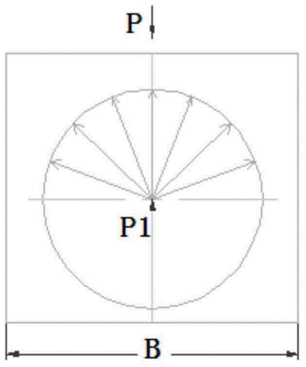
[0018] refer to figure 1 , the structure of the prior art rolling mill backup roll chock is that a through hole is opened in the chock, the bearing is installed in the hole, the circular hole in the middle is used for installing the bearing, the chock (horizontal) width is B, and P is The pressing force acts on the middle of the bearing seat, and the direction is from top to bottom; P1 is the rolling force borne by the bearing.

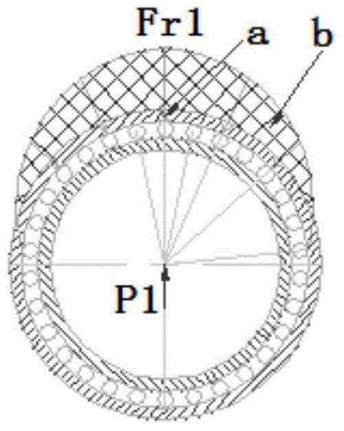
[0019] refer to figure 2 , is the structural force diagram of the existing bearing seat, the force distribution of the rolling elements inside the bearing is, b in the figure is the force distribution curve of other rolling elements, and a in the figure is the position of the single rolling element with the largest force, The maximum force Fr1=0.146P, it can be seen that the pressing force P concentrates on the mi...


PUM


Abstract

The invention discloses a supporting roll bearing base. A bearing hole is formed in the bearing base, the bearing hole is internally provided with a bearing, the bearing parallel with the upper part of the bearing hole is axially provided with a transparent arc-shaped through hole, the upper edges of two sides of the bearing base are respectively provided with a step along the axial direction of the bearing, the height of each step is 2 / 3 of the radius of a bearing outer ring. According to the structure, under the existing conditions that the size of the reduction force P and the direction of the roll force can not be changed, the force bearing point location of the bearing base is partly changed, part of supporting stiffness of the bearing base is changed on the maximal stress location of the bearing, so that the loading is uniformly bore by a roller in the bearing as far as possible, the peak load of a bearing rolling body is greatly reduced, the problems that the bearing is untimely burned and the life is obviously shortened are avoided.

Description

technical field [0001] The invention belongs to the technical field of metallurgical machinery and equipment, and relates to a support roller bearing seat. Background technique [0002] Under the existing technical conditions, although the bearings are accurately designed and selected according to the current rolling mill design theory, the service life of the rolling mill backup roll bearings is still far below its theoretical life because the mounting seat structure of the rolling mill backup roll bearings adopts the traditional support method , The premature failure of the bearing seriously plagues the safe operation of the rolling mill equipment. According to statistics, in the field of steel rolling, the early failure rate of rolling mill back-up roll bearings is as high as 50-90%, resulting in economic losses of up to billions of dollars per year. Contents of the invention [0003] The purpose of the present invention is to provide a back-up roll bearing seat, which...

Claims


Application Information

Patent Timeline
Patent Type & Authority Applications(China)
IPC IPC(8): F16C35/067B21B31/02
Inventor 焦文生郜松亮郭瑞林付大鹏
Owner MCC SFRE HEAVY IND EQUIP
Why Eureka
Try Eureka