A gas damping hydraulic pipeline vibration damping pipe clamp

A hydraulic pipeline and gas damping technology, which is applied in the direction of pipes/pipe joints/fittings, pipe supports, vibration suppression adjustment, etc., can solve problems such as collision and friction between pipelines and pipe clamps, loose pipe clamps, and pipeline surface wear , to achieve the effect of reducing the loosening of fixing bolts, prolonging the service life and avoiding loosening

Inactive Publication Date: 2016-10-05
YANSHAN UNIV
View PDF5 Cites 0 Cited by
  • Summary
  • Abstract
  • Description
  • Claims
  • Application Information

AI Technical Summary

Problems solved by technology

Especially for traditional fixed pipe clamps, the friction between the pipeline and the pipe clamp is more serious, which will not only cause the pipe clamp to loosen, but also cause obvious wear on the surface of the pipeline and cause damage to the pipeline
In some hydraulic pipelines with large pressure pulsation, there will also be failures of pipe wall bursting

Method used


Image

  • A gas damping hydraulic pipeline vibration damping pipe clamp
  • A gas damping hydraulic pipeline vibration damping pipe clamp
  • A gas damping hydraulic pipeline vibration damping pipe clamp

Examples


Embodiment Construction

[0014] The present invention will be further described below in conjunction with accompanying drawing:

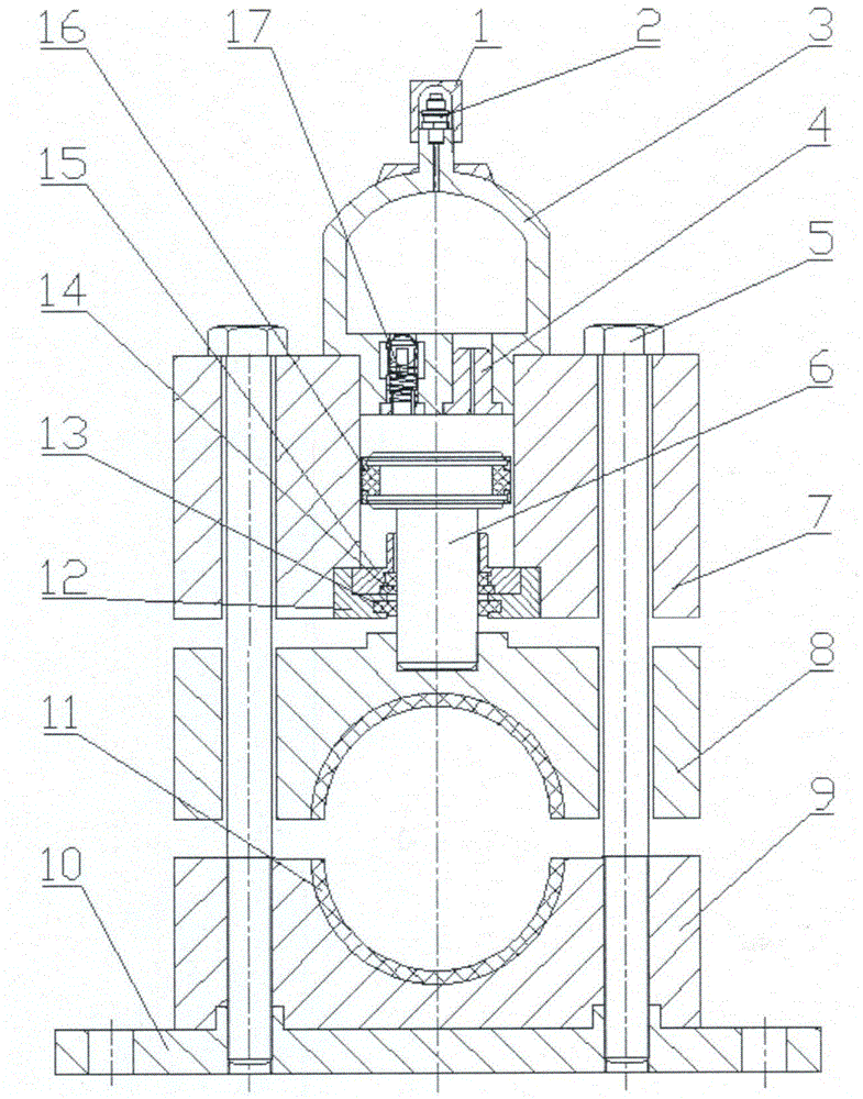
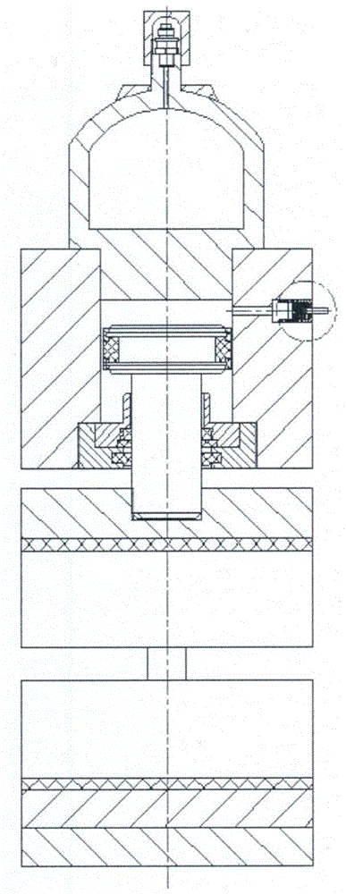
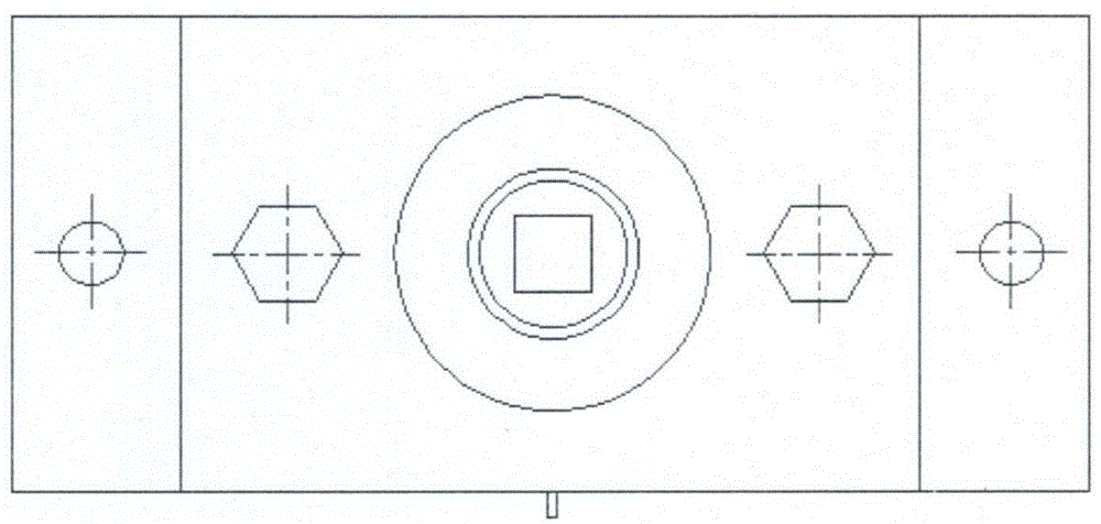
[0015] exist figure 1 , figure 2 and image 3 In the schematic diagram of a gas damping hydraulic pipeline damping pipe clamp shown, there are through holes for fasteners on the lower cover plate 10 of the pipe clamp, and two identical holes are arranged inside the through hole of the lower cover plate of the pipe clamp screw holes, and the upper opening of each screw hole is provided with a boss for positioning. A lower pipe clamp 9 is arranged on the lower cover plate of the pipe clamp. The lower pipe clamp is provided with a semi-cylindrical groove with an upward opening on the upper part of the cuboid base body. noodle. A damping material layer 11 corresponding to the radius of curvature is arranged in the semi-cylindrical groove of the lower pipe clip. There are two vertical screw holes on both sides of the semi-cylindrical groove of the lower pipe clamp. The ou...


PUM


Abstract

A gas damping type shock absorption pipe clamp for a hydraulic pipeline is mainly characterized in that a lower pipe clamp is arranged on a lower pipe clamp cover plate, and the upper portion of the lower pipe clamp is provided with a semicylindrical groove with the open side up; an upper pipe clamp matched with the lower pipe clamp is arranged above the lower pipe clamp, and the middle of the upper plane of the upper pipe clamp is provided with a threaded hole in threaded connection with the lower end of a plunger rod; the plunger rod is arranged in a central through hole of the upper pipe clamp cover plate, and a guide seal component is arranged between the plunger rod and the central through hole of the upper pipe clamp cover plate; the upper periphery of the plunger rod is provided with a combined slide ring seal part in contact with the central through hole of the upper pipe clamp cover plate, and the central through hole of the upper pipe clamp cover plate is in threaded connection with the lower portion of a gas cylinder; a gas check valve and a damping part are arranged in two threaded holes of the lower portion of the gas cylinder respectively, and the upper end of the gas cylinder is provided with an inflation valve; the upper pipe clamp cover plate, the upper pipe clamp, the lower pipe clamp and the lower pipe clamp cover plate are connected through two screw rods. The gas damping type shock absorption pipe clamp for the hydraulic pipeline has the advantages that the defects of low reliability and high impact of a traditional pipe clamp to a pipeline system are overcome, and vibration of the hydraulic pipeline can be well eliminated.

Description

technical field [0001] The invention relates to a pipe clip of a hydraulic pipeline. Background technique [0002] Pipelines are the basic elements of liquid power transmission systems and are widely used in various industrial fields. In the actual working conditions of the pipeline system, the vibration of the pipeline will be caused by the structural characteristics of the hydraulic pump, the compressibility of the oil, the vibration transmission of the fluid conveying machinery, and the frequent opening or closing of the valve in the pipeline. In large-scale pipeline systems, the resonance of the pipeline is more prominent. It will not only cause structural fatigue failure, but even cause damage to the pipeline system, resulting in significant economic losses. The vibration of the pipeline is mainly caused by the fluid inside the pipeline and the external equipment connected to the pipeline. The control of its vibration is mainly divided into active control and passive ...

Claims


Application Information

Patent Timeline
Patent Type & Authority Patents(China)
IPC IPC(8): F16L3/10F16F15/023
CPCF16F15/023F16L3/10
Inventor 权凌霄郭长虹刘嵩宋豫孔祥东
Owner YANSHAN UNIV
Why Eureka
Try Eureka