Light guide and lighting device using the light guide

A light guide and lighting technology, applied in the light guide, light guide, optics and other directions of the lighting system, can solve the problems of uneven display and uneven light, and achieve the effect of improving the shading rate and reducing the uneven light.

Active Publication Date: 2018-03-30
ALPS ALPINE CO LTD
View PDF7 Cites 0 Cited by
  • Summary
  • Abstract
  • Description
  • Claims
  • Application Information

AI Technical Summary

Problems solved by technology

However, due to the structure of the sheet-shaped light guide 911, it is difficult to cover the inner wall surface of the slit S with the light-shielding material 918 due to progress in miniaturization and space saving, and light leakage cannot be reduced only through the slit S. , it is possible to cause light unevenness in each display area (illumination area), and cause display unevenness in each display area

Method used


Image

  • Light guide and lighting device using the light guide
  • Light guide and lighting device using the light guide
  • Light guide and lighting device using the light guide

Examples


no. 1 Embodiment approach

[0061] The light guide 100 of the first embodiment will be described below.

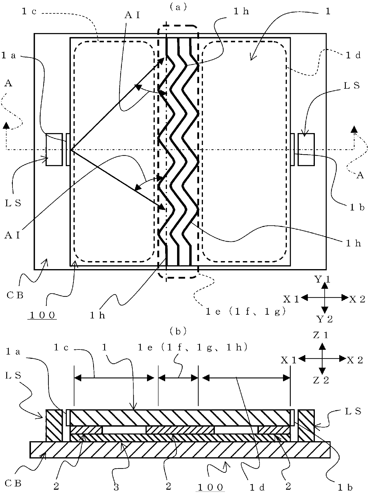
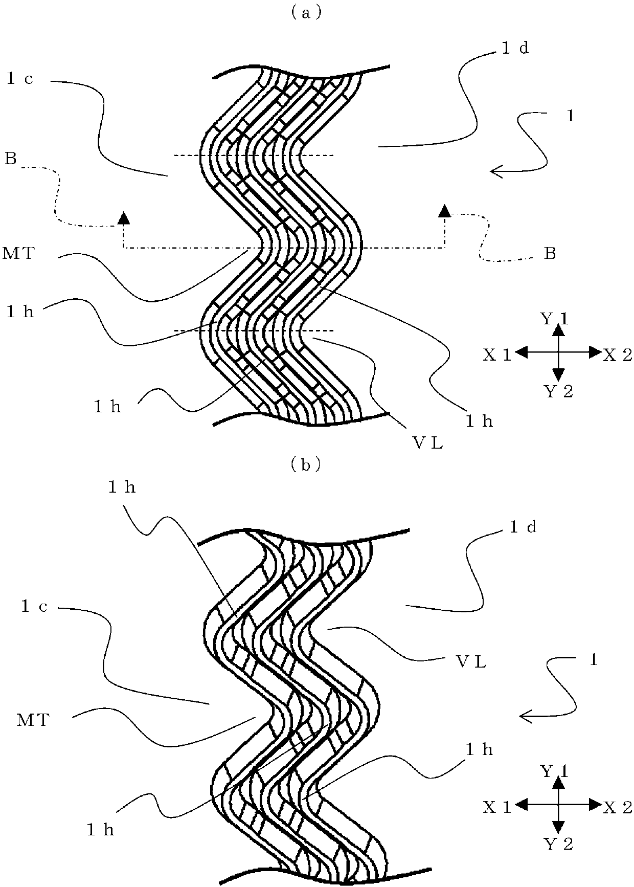
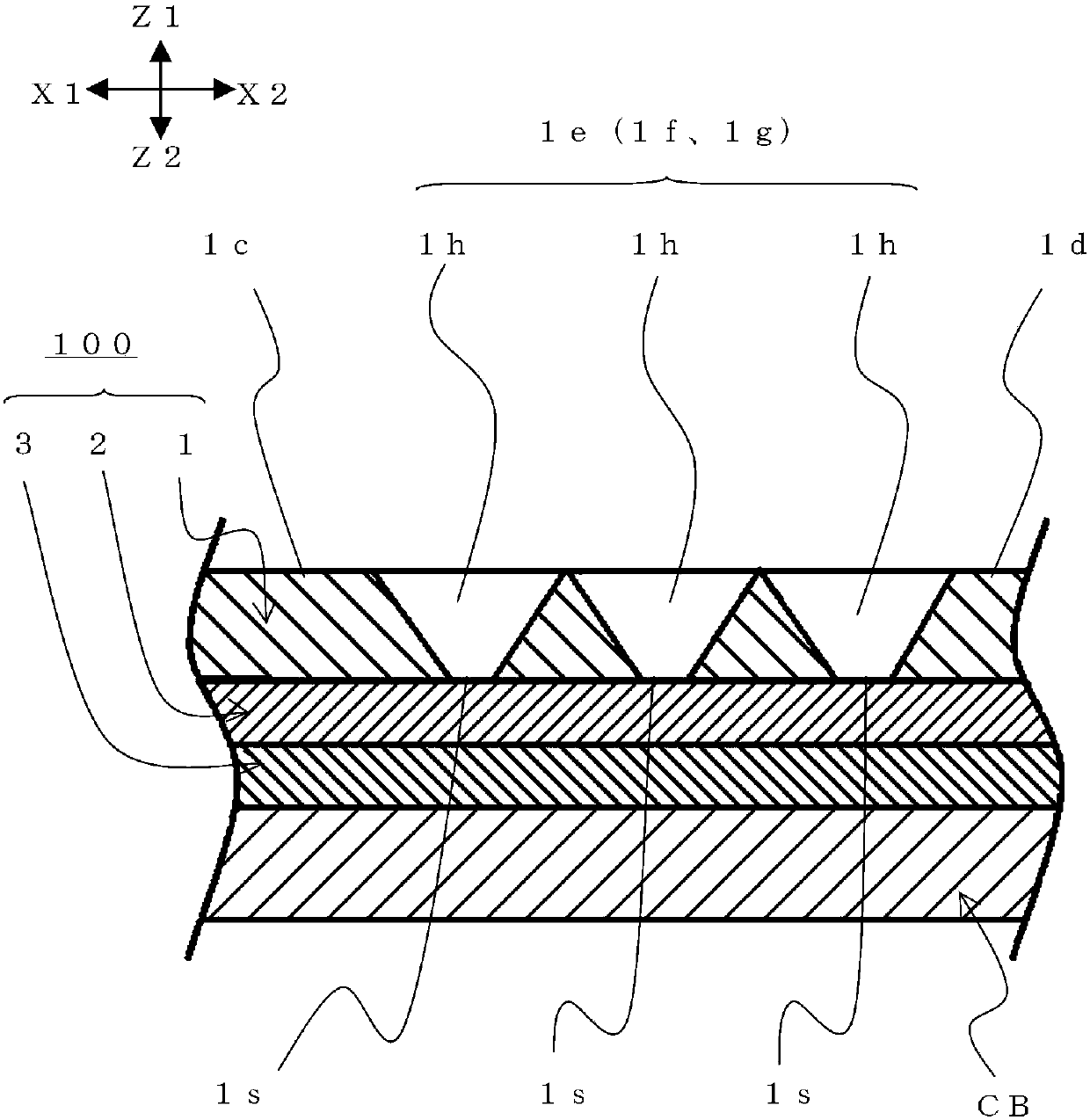
[0062] First, use Figure 1 to Figure 3 The structure of the light guide 100 of this embodiment will be described. figure 1 It is a figure which shows the light guide 100 of 1st Embodiment, figure 1 (a) is a schematic plan view showing the appearance of the light guide 100, figure 1 (b) is figure 1 A cross-sectional view of line AA described in (a). figure 2 It is a figure which shows the corrugated part of the 1st slit 1h in 1st Embodiment, figure 2 (a) is an enlarged plan view showing the first slit 1h, figure 2 (b) is an enlarged perspective view showing the first slit 1h. image 3 yes figure 2 A schematic cross-sectional view of line BB described in .

[0063] Such as figure 1 As shown, the light guide 100 includes a base member 1, a light shielding member 2, and a reflection member 3, and is arranged on a substrate CB together with a light source LS.

[0064] The base member 1...

no. 2 Embodiment approach

[0093] The light guide 200 of the second embodiment will be described below. In the light guide 200 of the second embodiment, the first slit region 1f of the light guide 100 of the first embodiment is different. Except for the first slit region 1f, the light guide 100 of the first embodiment is the same as the light guide 200 of the second embodiment in terms of components and structures. In the following description, parts different from those of the light guide 100 of the first embodiment will be described, and the names and symbols used in the light guide 100 of the first embodiment will be used for descriptions of common components and parts.

[0094] First, use Figure 5 to Figure 7 The structure of the light guide 200 of the second embodiment will be described. Figure 5 It is a figure which shows the light guide 200 of 2nd Embodiment, Figure 5 (a) is a schematic plan view showing the appearance of the light guide 200, Figure 5 (b) means Figure 5 Cross-sectional ...

no. 3 Embodiment approach

[0114] The light guide 300 of the third embodiment will be described below. In the light guide 300 of the third embodiment, the structure of the base member 1 of the light guide 100 of the first embodiment is different from that of the light guide 200 of the second embodiment. The light guide 100 of the first embodiment, the light guide 200 of the second embodiment, and the light guide 300 of the third embodiment have the same components and configurations except for the base member 1 . In the following description, parts different from the light guide 100 of the first embodiment and the light guide 200 of the second embodiment will be described, and the light guide 100 of the first embodiment and the light guide 200 of the second embodiment will be used for common components and parts. Names and symbols used in the light guide 200 of the embodiment will be described.

[0115] First, use Figure 9 to Figure 11 The structure of the light guide 300 of the third embodiment will...


PUM


Abstract

Provided are a light guide capable of realizing illumination with reduced unevenness of light in each illumination region, and an illumination device using the light guide. The light guide (100) is composed of a light-transmitting base member (1), and has a first light-emitting area (1c) corresponding to the first light-incidence portion (1a) and a second light-emitting area (1c) corresponding to the second light-incidence portion (1b). In the light-emitting area (1d), the boundary area (1e) between the first light-emitting area and the second light-emitting area is formed with a first slit area (1f), one of the first light-incident portion or the second light-incidence portion Formed on the side opposite to the first slit area across the first illuminated area or the second illuminated area, in the light guide, the first slit area has a first slit (1h), and the first slit is opposite to the first slit area The direction in which the traveling direction of the light from the light source (LS) intersects extends, and the intersection angle with the light from the light source changes continuously, and the width of the first slit becomes wider as it goes downward or upward.

Description

technical field [0001] The present invention relates to a light guide and an illuminating device using the light guide, in particular to a light guide with multiple illuminating areas and an illuminating device using the light guide. Background technique [0002] An operation unit or the like of an electronic device is often equipped with a lighting function. In addition, as the lighting function, the light source is often arranged at a position far from the irradiated part, and a light guide is used to guide the light to the irradiated part. Recently, there are many operation units having a plurality of display areas, and light guides for illuminating each display area and lighting devices using the light guides are required. As such a light guide, a sheet-shaped light guide (light guide) described in Patent Document 1 described below is known. [0003] Below, use Figure 16 , the sheet-shaped light guide described in Patent Document 1 will be described. Figure 16 It is ...

Claims


Application Information

Patent Timeline
Patent Type & Authority Patents(China)
IPC IPC(8): G02B6/00F21V8/00
Inventor 伊藤睦夫伊势和贵
Owner ALPS ALPINE CO LTD
Why Eureka
Try Eureka