Tension adjusting method for fiber traction laying

A technology of tension adjustment and optical fiber, which is applied in the direction of optical fiber/cable installation, etc., can solve the problems of increased fiber damage and breakage, optical cable surge, damage, etc., to avoid looping and surge, tension is always stable, and improve use The effect of longevity

Inactive Publication Date: 2015-09-02
成都亨通光通信有限公司
View PDF7 Cites 4 Cited by
  • Summary
  • Abstract
  • Description
  • Claims
  • Application Information

AI Technical Summary

Problems solved by technology

[0003] During the long-distance laying of the optical cable, due to the distance factor, the strength of the optical cable will increase with the increase of the distance, so the part of the optical cable may be partially damaged due to the concentration of stress. The optical cable is prone to surge phenomenon at the exit of the cable reel, which makes the middle part of the optical cable and the end of the optical cable loop, that is, it is likely to cause the bending radius of the optical cable to be less than 15 to 20 times its outer diameter, which increases the damage to the optical fiber. possibility of fracture

Method used


Image

  • Tension adjusting method for fiber traction laying
  • Tension adjusting method for fiber traction laying

Examples


Embodiment 1

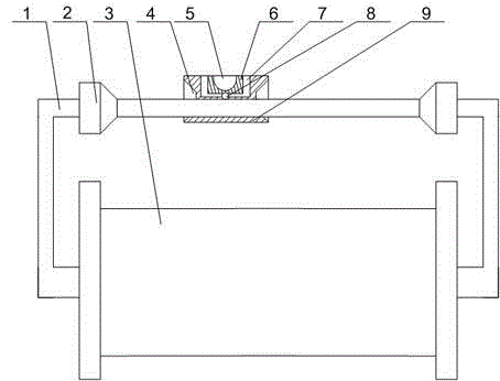
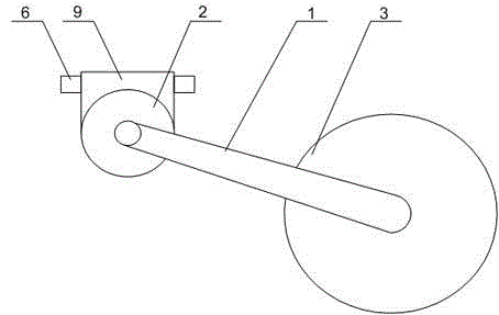
[0025] Such as figure 1 and figure 2 As shown, this embodiment includes the following steps,

[0026] (A) Place the cable head on the cable reel 3 in the wire slot 5, and start laying the predetermined line of the optical cable through the wire slot 5. The optical cables on the cable drum 3 are distributed layer by layer, so the traction of the optical cable follows the axis of the cable drum 3 The direction starts to be pulled out layer by layer;

[0027] (B) Slide the adjusting block 9 on the connecting rod 1, and the adjusting block 9 starts to slide on the connecting rod 1 along with the outlet direction of the optical cable on the cable reel 3. By adjusting the outlet of the optical cable, the optical cable is further reduced. The phenomenon that the axial direction of disk 3 swings greatly;

[0028] (C), the adjusting block 9 is eccentric relative to the connecting rod 1, that is, the center of gravity of the adjusting block 9 is not on the connecting rod 1, thereby ...


PUM


Abstract

The invention discloses a tension adjusting method for fiber traction laying. The gravity of an adjustment block is always disposed above a connecting rod, the tension of an optical cable on a cable tray during traction is always stable, and at the same time, a traction block is rotationally arranged in a rectangular groove through a universal ball, such that a fiber can realize radial swing within a certain scope, large-amplitude swing of the optical cable, caused by a traction strength increase during long-distance laying can be buffered, the tension strength of the optical cable at the cable tray is timely adjusted during the long-distance laying, and optical cable swirling and surge phenomena are avoided.

Description

technical field [0001] The invention relates to the field of optical cable laying, in particular to a tension adjustment method for optical fiber traction laying. Background technique [0002] In daily life, optical fibers are used for long-distance information transmission because the loss of light in optical fibers is much lower than that of electricity in wires. Most optical fibers must be covered by several layers of protective structures before use. The coated cable is called an optical cable. The protective layer and insulating layer on the outer layer of the optical fiber can prevent the surrounding environment from harming the optical fiber, such as water, fire, electric shock, etc. . [0003] During the long-distance laying of the optical cable, due to the distance factor, the strength of the optical cable will increase with the increase of the distance, so the part of the optical cable may be partially damaged due to the concentration of stress. The optical cable...

Claims


Application Information

Patent Timeline
Patent Type & Authority Applications(China)
IPC IPC(8): G02B6/46
CPCG02B6/46
Inventor 孙义兴王耀明许建国彭志勇刘东李涛
Owner 成都亨通光通信有限公司
Why Eureka
Try Eureka