Sliding gate type distribution cabinet

A power distribution cabinet and sliding door technology, applied in the direction of the substation/distribution device shell, etc., can solve the problems of transfer trouble, power distribution cabinet door obstruction, confusion, etc., to avoid heavy work and improve safety.

Inactive Publication Date: 2015-09-02
廖婕
View PDF5 Cites 3 Cited by
  • Summary
  • Abstract
  • Description
  • Claims
  • Application Information

AI Technical Summary

Problems solved by technology

[0002] For some large-scale power distribution, in order to increase the stability of the power distribution cabinet during the transfer process, the lifting ring will be set on the top of the power distribution cabinet. During the transfer process, it needs to be lifted and moved through the lifting ring on the top of the power distribution cabinet; The height of the electric cabinet is high, so people need to climb to the top of the power distribution cabinet with the help of ladders or other tools, and hook the crane hook to the lifting ring, which will undoubtedly bring a lot of trouble to the transfer. safety hazard of falling
Moreover, the power distribution cabinet is generally used to load multiple lines. The interior of the prior art power distribution cabinet is generally an integrated structure. After multiple lines enter, it is easy to cause confusion. Once the lines are chaotic, there will be danger. In severe cases, it even threatens people's lives
Moreover, the doors of the current power distribution cabinets are usually opened to both sides, so that when the operator needs to open the power distribution cabinet to adjust and maintain the circuit in the power distribution cabinet, the doors of the adjacent power distribution cabinets will be blocked and cannot be opened. Cabinet doors that are fully open and open left and right tend to take up space, resulting in a waste of space

Method used


Image

  • Sliding gate type distribution cabinet
  • Sliding gate type distribution cabinet
  • Sliding gate type distribution cabinet

Examples


Embodiment Construction

[0012] The following will clearly and completely describe the technical solutions in the embodiments of the present invention with reference to the accompanying drawings in the embodiments of the present invention. Obviously, the described embodiments are only some, not all, embodiments of the present invention. Based on the embodiments of the present invention, all other embodiments obtained by persons of ordinary skill in the art without making creative efforts belong to the protection scope of the present invention.

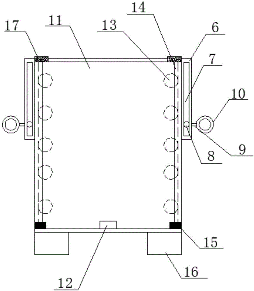
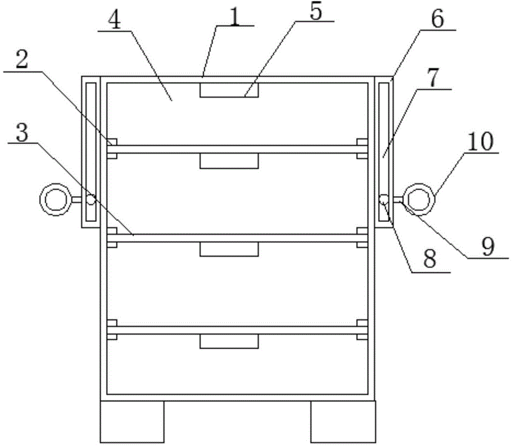
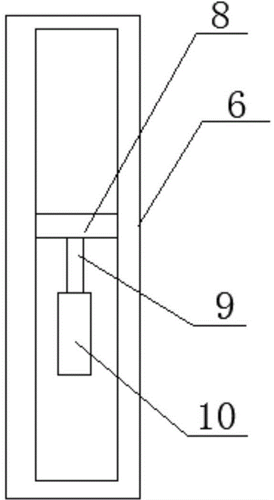
[0013] see Figure 1~3 , in an embodiment of the present invention, a sliding door type power distribution cabinet includes a cabinet body 1 and a cabinet door 11. Several sets of slide rails 2 are provided inside the cabinet body 1, and each set of slide rails 2 is provided with A partition 3, the partition 3 divides the cabinet body into several cavities 4, the partition 3 is provided with at least two and each partition 3 is provided with a through-wire hol...


PUM


Abstract

Disclosed in the invention is a sliding gate type distribution cabinet comprising a cabinet body. A plurality of groups of sliding rails are arranged inside the cabinet body; and one separation board is arranged on each sliding rail group. The cabinet body is divided into a plurality of cavities by the separation board and a temperature and humidity controller is arranged at the upper end of each cavity. Chutes are formed in the front and rear sides of the upper ends of the left side and the right side of the cabinet body; rectangular slots are formed in the front and rear sides of the chutes; and rotating shafts are arranged in the rectangular slots and are connected with hanging rings by connecting rods. A second sliding rail is arranged at the front side of a cabinet door; a plurality of rollers cooperating with the second sliding rail are arranged at the left side and the right side of the cabinet door; and a position switch is arranged at the lower end of the cabinet door. Besides, a cylinder is arranged at the lower end of the cabinet body; and the upper end of the cylinder is connected with the lower end of the cabinet door. Positioning bars are arranged at the lower end of the outer side of the cabinet door; and clamp bars are arranged at the outer side of the upper end of the second sliding rail. The provided distribution cabinet has advantages of simple structure, convenient usage, convenient lifting, high security, organized wiring, prevented messy phenomenon, and convenient door opening.

Description

technical field [0001] The invention relates to the technical field of electric equipment, in particular to a sliding door type power distribution cabinet. Background technique [0002] For some large-scale power distribution, in order to increase the stability of the power distribution cabinet during the transfer process, the lifting ring will be set on the top of the power distribution cabinet. During the transfer process, it needs to be lifted and moved through the lifting ring on the top of the power distribution cabinet; The height of the electric cabinet is high, and it is necessary for people to climb to the top of the power distribution cabinet with the help of ladders or other tools, and hook the driving hook to the lifting ring, which will undoubtedly bring a lot of trouble to the transfer. Safety hazard of falling. Moreover, the power distribution cabinets are generally used to load multiple lines. The interior of the prior art power distribution cabinets is gene...

Claims


Application Information

Patent Timeline
Patent Type & Authority Applications(China)
IPC IPC(8): H02B1/26
CPCH02B1/26H02B1/30
Inventor 廖婕
Owner 廖婕
Why Eureka
Try Eureka