Thermostat

A thermostat and burner technology, applied in the field of thermostats, can solve problems such as component wear and gas leakage

Active Publication Date: 2015-09-02
E G O 电动工具有限公司
View PDF5 Cites 4 Cited by
  • Summary
  • Abstract
  • Description
  • Claims
  • Application Information

AI Technical Summary

Problems solved by technology

[0012] Furthermore, the relative movement between the parts may cause wear phenomena which may over time cause gas to leak through the valve, requiring it to be replaced

Method used


Image

  • Thermostat
  • Thermostat
  • Thermostat

Examples


Embodiment Construction

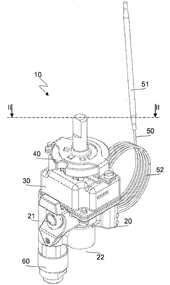
[0027] refer to figure 1 , The thermostat 10 according to the invention comprises a body 20 inside which are formed a plurality of ducts suitable for supplying a gas flow from an inlet opening 21 to an outlet opening 22 to a burner (not shown). The inlet opening is for connection to a gas source and the outlet opening is for connection to the burner through a suitable conduit.

[0028] The thermostat 10 also includes a bell 30 secured to the body 20, for example by screws, which rotatably supports a coupling member 40 configured to allow the installation of knobs (not shown) for ignition and temperature adjustment of the burner. out).

[0029] The thermostat 10 further comprises a thermostatic package 50 equipped with a probe 51 for insertion in a compartment to be heated, for example a compartment of an oven. A conduit 52 filled with a heat-expandable fluid medium (eg diathermy oil) is connected to the probe 51 of the thermostat 50 . The thermostatic pack 50 also includes ...


PUM


Abstract

The invention relates to a thermostat (10) for cooking appliances powered by gas, said thermostat (10) comprising a body (20) within which there are formed an inlet conduit (23) and an outlet conduit (24), suitable to receive a gas flow from a supply source and to supply such a gas flow to a gas burner, respectively, as well as a chamber (25) with a substantially cylindrical shape arranged in fluid communication with said inlet conduit (23). The chamber (25) is also arranged in fluid communication with said outlet conduit (24) either directly, through a main opening (70) formed at one end thereof, or indirectly, through a secondary conduit (71) that is formed in the body (20) of the thermostat (10) and flows into the outlet conduit (24) bypassing said main opening (70), said main opening and secondary conduit (70, 71) being respectively dimensioned for a maximum and a minimum flow rate of gas. The thermostat (10) further comprises a one-piece valve (80) for adjusting the gas flow rate, the valve being coaxially fitted in the chamber (25) and guided by its peripheral walls. Thanks to these features, the structural configuration of the thermostat body and its conduits is much more compact, functional and cheap than the structural configuration of thermostats known in the art.

Description

technical field [0001] The present invention relates generally to the field of gas cooking appliances, and more particularly to a thermostat for a gas cooking appliance. Background technique [0002] A thermostat is used to maintain a desired temperature in an enclosed compartment such as that of an oven in which a gas fueled burner provides the heat energy required for cooking. Maintaining the desired temperature is possible thanks to the use of a thermostatic package fitted into the heated compartment which allows the supply of The gas flow to the burner is adjusted retrospectively. [0003] In the body of the thermostats known in the prior art, a plurality of ducts are usually formed, which define a first circuit for supplying the gas to the nozzle generating the pilot flame and for feeding the gas into the Secondary circuit to burner. The first circuit is characterized by a predetermined minimum gas flow, usually controlled by a needle valve and adjusting screw, while...

Claims


Application Information

Patent Timeline
IPC IPC(8): F23K5/00F23N5/14F23N5/02
CPCF23N2035/18F23K5/007F23K2900/05002F23N2035/24F23K2401/201F23N5/146F23N5/025F23N2235/18F23N2235/24F23K2400/201F23N5/14F24C3/12G05D23/02
Inventor D·贝萨蒂M·杜尼亚尼L·比达迪M·塔帕
Owner E G O 电动工具有限公司
Why Eureka
Try Eureka